Toyota Camry (XV70): Transmission Control Switch Circuit
DESCRIPTION
When the shift lever is in S and moved toward "-" or "+", it is possible to select different shift ranges (S1 to S8).
Moving the shift lever toward "+" increases the shift range by one, and moving the shift lever toward "-" decreases the shift range by one.
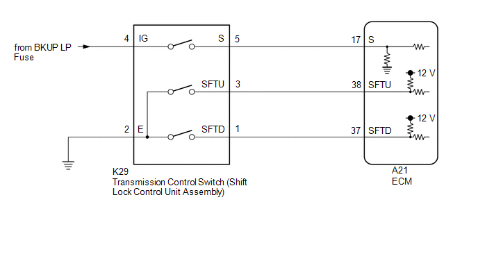
WIRING DIAGRAM
CAUTION / NOTICE / HINT
NOTICE:
Inspect the fuses for circuits related to this system before performing the following procedure.
PROCEDURE
| 1. |
READ VALUE USING TECHSTREAM (Shift SW Status (S Range)) |
(a) Connect the Techstream to the DLC3.
(b) Turn the engine switch on (IG).
(c) Turn the Techstream on.
(d) Enter the following menus: Powertrain / Engine / Data List / Shift SW Status (S Range).
(e) Read the Data List according to the display on the Techstream.
Powertrain > Engine > Data List|
Tester Display | Measurement Item |
Range | Normal Condition |
Diagnostic Note |
|---|---|---|---|---|
|
Shift SW Status (S Range) |
Sport (S) mode select switch status |
ON or OFF |
| - |
|
Tester Display |
|---|
| Shift SW Status (S Range) |
|
Result | Proceed to |
|---|---|
|
Data List value is normal |
A |
| Data List value is not normal |
B |
| B |
.gif) | GO TO STEP 6 |
|
.gif)
| 2. |
READ VALUE USING TECHSTREAM (SPORT SHIFT UP SW AND SPORT SHIFT DOWN SW) |
(a) Connect the Techstream to the DLC3.
(b) Turn the engine switch on (IG).
(c) Turn the Techstream on.
(d) Enter the following menus: Powertrain / Engine / Data List / Sport Shift Up SW and Sport Shift Down SW.
(e) Read the Data List according to the display on the Techstream.
Powertrain > Engine > Data List|
Tester Display | Measurement Item |
Range | Normal Condition |
Diagnostic Note |
|---|---|---|---|---|
|
Sport Shift Up SW | Sport shift up switch status |
ON or OFF |
| - |
|
Sport Shift Down SW | Sport shift down switch status |
ON or OFF |
| - |
|
Tester Display |
|---|
| Sport Shift Up SW |
|
Sport Shift Down SW |
|
Result | Proceed to |
|---|---|
|
Data List values are normal |
A |
| Data List values are not normal |
B |
| A |
| PROCEED TO NEXT SUSPECTED AREA SHOWN IN PROBLEM SYMPTOMS TABLE |
|
| 3. |
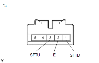
INSPECT TRANSMISSION CONTROL SWITCH (SHIFT LOCK CONTROL UNIT ASSEMBLY) |
(a) Disconnect the K29 transmission control switch connector.
| (b) Measure the resistance according to the value(s) in the table below. Standard Resistance:
|
|
| NG | | REPLACE TRANSMISSION CONTROL SWITCH (SHIFT LOCK CONTROL UNIT ASSEMBLY) |
|
| 4. |
CHECK HARNESS AND CONNECTOR (TRANSMISSION CONTROL SWITCH - BODY GROUND) |
(a) Disconnect the K29 transmission control switch connector.
(b) Measure the resistance according to the value(s) in the table below.
Standard Resistance:
|
Tester Connection | Condition |
Specified Condition |
|---|---|---|
|
K29-2 (E) - Body ground |
Always | Below 1 Ω |
| NG | | REPAIR OR REPLACE HARNESS OR CONNECTOR (TRANSMISSION CONTROL SWITCH - BODY GROUND) |
|
| 5. |
CHECK HARNESS AND CONNECTOR (TRANSMISSION CONTROL SWITCH - ECM) |
(a) Connect the K29 transmission control switch connector.
(b) Disconnect the A21 ECM connector.
(c) Measure the resistance according to the value(s) in the table below.
Standard Resistance:
|
Tester Connection | Condition |
Specified Condition |
|---|---|---|
|
A21-38 (SFTU) - Body ground |
Shift lever held in "+" (Up shift) |
Below 1 Ω |
|
A21-38 (SFTU) - Body ground |
Shift lever not held in "+" (Up shift) |
10 kΩ or higher |
|
A21-37 (SFTD) - Body ground |
Shift lever held in "-" (Down shift) |
Below 1 Ω |
|
A21-37 (SFTD) - Body ground |
Shift lever not held in "-" (Down shift) |
10 kΩ or higher |
| OK | | PROCEED TO NEXT SUSPECTED AREA SHOWN IN PROBLEM SYMPTOMS TABLE |
| NG | | REPAIR OR REPLACE HARNESS OR CONNECTOR (TRANSMISSION CONTROL SWITCH - ECM) |
| 6. |
INSPECT TRANSMISSION CONTROL SWITCH (SHIFT LOCK CONTROL UNIT ASSEMBLY) |
| (a) Disconnect the K29 transmission control switch connector. |
|
(b) Measure the resistance according to the value(s) in the table below.
Standard Resistance:
|
Tester Connection | Condition |
Specified Condition |
|---|---|---|
|
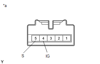
4 (IG) - 5 (S) | Shift lever in S, "+" or "-" |
Below 1 Ω |
|
Shift lever not in S, "+" or "-" |
10 kΩ or higher |
| NG | | REPLACE TRANSMISSION CONTROL SWITCH (SHIFT LOCK CONTROL UNIT ASSEMBLY) |
|
| 7. |
CHECK HARNESS AND CONNECTOR (TRANSMISSION CONTROL SWITCH (POWER SOURCE)) |
(a) Disconnect the K29 transmission control switch connector.
(b) Turn the engine switch on (IG).
(c) Measure the voltage according to the value(s) in the table below.
Standard Voltage:
|
Tester Connection | Condition |
Specified Condition |
|---|---|---|
|
K29-4 (IG) - Body ground |
Engine switch on (IG) |
11 to 14 V |
| NG | | REPAIR OR REPLACE HARNESS OR CONNECTOR (TRANSMISSION CONTROL SWITCH (POWER SOURCE)) |
|
| 8. |
CHECK HARNESS AND CONNECTOR (TRANSMISSION CONTROL SWITCH - ECM) |
(a) Disconnect the K29 transmission control switch connector.
(b) Disconnect the A21 ECM connector.
(c) Measure the resistance according to the value(s) in the table below.
Standard Resistance:
|
Tester Connection | Condition |
Specified Condition |
|---|---|---|
|
K29-5 (S) - A21-17 (S) |
Always | Below 1 Ω |
|
K29-5 (S) or A21-17 (S) - Body ground and other terminals |
Always | 10 kΩ or higher |
| OK | | PROCEED TO NEXT SUSPECTED AREA SHOWN IN PROBLEM SYMPTOMS TABLE |
| NG | | REPAIR OR REPLACE HARNESS OR CONNECTOR (TRANSMISSION CONTROL SWITCH - ECM) |
READ NEXT:
 Shift Paddle Switch Circuit
DESCRIPTION Moving the shift lever to S enables the shift range to be selected. The shift range can be selected by operating the "+" or "-" shift paddle switch. WIRING DIAGRAM
CAUTION / NOTICE / HI
Components
COMPONENTS ILLUSTRATION
*1 NO. 1 OIL COOLER OUTLET TUBE SUB-ASSEMBLY
*2 NO. 1 TRANSMISSION OIL FILLER TUBE
*3 OIL COOLER UNION SUB-ASSEMBLY
*4 OVERFLOW PLUG
SEE MORE:
Operation Check
OPERATION CHECK CHECK NAVIGATION SYSTEM NORMAL CONDITION
(a) If the cause of a symptom is any of the following, the corresponding symptom is normal; it is not due to a malfunction.
Symptom Answer
A longer route than expected is chosen.
Depending on the road conditions, the na
Brake System Control Module "A" System Voltage System Voltage High (C137BA3)
DESCRIPTION If a malfunction is detected in the power supply circuit, the skid control ECU (brake actuator assembly) stores this DTC and the fail-safe function prohibits ABS operation.
This DTC is stored when the +BS terminal voltage deviates due to a malfunction in a power supply or charging syst
