Toyota Camry (XV70): Turn Signal Switch Circuit
DESCRIPTION
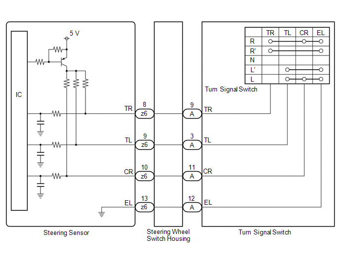
The steering sensor receives the turn signal switch information and controls the turn signal lights.
WIRING DIAGRAM
PROCEDURE
|
1. | READ VALUE USING TECHSTREAM |
(a) Connect the Techstream to the DLC3.
(b) Turn the ignition switch to ON.
(c) Turn the Techstream on.
(d) Enter the following menus: Chassis / Steering Angle Sensor / Data List.
(e) Read the Data List according to the display on the Techstream.
Chassis > Steering Angle Sensor > Data List|
Tester Display | Measurement Item |
Range | Normal Condition |
Diagnostic Note |
|---|---|---|---|---|
|
Turn Signal Switch (Right) |
Turn signal switch (right turn position) signal |
OFF or ON | OFF: Turn signal switch not in right turn position ON: Turn signal switch in right turn position |
- |
| Turn Signal Switch (Left) |
Turn signal switch (left turn position) signal |
OFF or ON | OFF: Turn signal switch not in left turn position ON: Turn signal switch in left turn position |
- |
| Cornering Light Switch |
Turn signal switch (full turn) signal |
OFF or ON | OFF: Turn signal switch not in left or right turn position ON: Turn signal switch in left or right full turn position |
- |
|
Tester Display |
|---|
|
Turn Signal Switch (Right) |
|
Turn Signal Switch (Left) |
|
Cornering Light Switch |
OK:
Normal conditions listed above are displayed.
| OK | .gif) |
PROCEED TO NEXT SUSPECTED AREA SHOWN IN PROBLEM SYMPTOMS TABLE
|
|
.gif)
|
2. | INSPECT TURN SIGNAL SWITCH |
(a) Remove the turn signal switch.
Click here
.gif)
(b) Inspect the turn signal switch.
Click here
| NG | |
REPLACE TURN SIGNAL SWITCH |
|
|
3. | INSPECT STEERING WHEEL SWITCH HOUSING |
(a) Remove the steering wheel switch housing.
Click here
(b) Inspect the steering wheel switch housing.
Click here
| OK | |
REPLACE STEERING SENSOR |
| NG | |
REPLACE STEERING WHEEL SWITCH HOUSING
|
READ NEXT:
 Automatic High Beam Switch Indicator does not Come ON
DESCRIPTION When the automatic high beam system is on, the main body ECU (multiplex network body ECU) illuminates the auto high beam switch indicator. WIRING DIAGRAM
CAUTION / NOTICE / HINT
NOT
Automatic High Beam System does not Operate or Operation Indicator does not Illuminate
DESCRIPTION The main body ECU (multiplex network body ECU) controls the automatic high beam system based on signals received from the forward recognition camera. WIRING DIAGRAM
CAUTION / NOTICE /
Headlight Dimmer Switch Circuit
DESCRIPTION The steering sensor receives the following switch information:
Light control switch in DRL OFF*, tail, head or AUTO position
Dimmer switch in high, low or high flash (pass) pos
SEE MORE:
Installation
INSTALLATION PROCEDURE 1. INSTALL FLOW SHUTTING VALVE (NO. 1 WATER BY-PASS HOSE)
(a) Install the flow shutting valve (No. 1 water by-pass hose) with the bolt.
Torque: 19 N·m {194 kgf·cm, 14 ft·lbf} (b) Connect the flow shutting valve connector.
(c) Connect the flow shutting valve (No. 1 wa
VIN Not Programmed (P063051)
MONITOR DESCRIPTION DTC P063051 is stored when the Vehicle Identification Number (VIN) is not stored in the ECM or the stored VIN is not accurate.
DTC No. Detection Item
DTC Detection Condition Trouble Area
MIL Memory
Note P063051
VIN Not Programmed Either of t
