Toyota Camry (XV70): Ultrasonic Sensor (Front Left Center) Missing Message (C1AE287)
DESCRIPTION
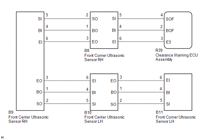
This DTC is stored when an open circuit or short occurs in the communication line between the front center ultrasonic sensor LH and the front center ultrasonic sensor RH, or when a malfunction occurs in the front center ultrasonic sensor LH.
|
DTC No. | Detection Item |
DTC Detection Condition | Trouble Area |
|---|---|---|---|
|
C1AE287 | Ultrasonic Sensor (Front Left Center) Missing Message |
Front center ultrasonic sensor LH lost communication |
|
WIRING DIAGRAM
CAUTION / NOTICE / HINT
NOTICE:
- Perform registration after replacing or removing and installing the ultrasonic sensor or clearance warning ECU assembly.
Click here
.gif)
- If a DTC is detected again after the repair, turn the ignition switch to ON and turn the intuitive parking assist system on, and then clear the DTC.
Click here
- If C1AE396 is output at the same time, check C1AE396 first.
Click here
PROCEDURE
|
1. | VEHICLE CONDITION AND WORK DETAILS CHECK |
(a) Check the vehicle condition and work details.
|
Result | Proceed to |
|---|---|
|
The clearance warning ECU assembly or ultrasonic sensor has not been replaced |
A |
| The clearance warning ECU assembly or ultrasonic sensor has been replaced |
B |
| B |
.gif) | GO TO CALIBRATION |
|
.gif)
| 2. |
CHECK CONNECTOR CONNECTION CONDITION (ULTRASONIC SENSOR) |
(a) Check that the connector is properly connected to the front corner ultrasonic sensor and front center ultrasonic sensor.
|
| 3. |
CHECK FOR DTC |
(a) Check for DTCs.
Body Electrical > Clearance Warning > Trouble Codes(b) According to the display on the GTS, clear the DTCs.
Body Electrical > Clearance Warning > Clear DTCs(c) Recheck for DTCs.
Body Electrical > Clearance Warning > Trouble Codes|
Result | Proceed to |
|---|---|
|
C1AE287 is not output |
A |
| C1AE287 is output |
B |
| A |
| END (CONNECTOR CONNECTION MALFUNCTION) |
|
| 4. |
CHECK CONNECTOR CONNECTION CONDITION (CLEARANCE WARNING ECU ASSEMBLY) |
(a) Check that the connector is properly connected to the clearance warning ECU assembly.
|
| 5. |
CHECK DTC OUTPUT |
(a) Check for DTCs.
Body Electrical > Clearance Warning > Trouble Codes(b) According to the display on the GTS, clear the DTCs.
Body Electrical > Clearance Warning > Clear DTCs(c) Recheck for DTCs.
Body Electrical > Clearance Warning > Trouble Codes DTC OUTPUT COMBINATION:|
Symptoms | DTC Detection | |||
|---|---|---|---|---|
|
C1AE487 | C1AE387 |
C1AE287 | C1AE187 | |
|
Symptom 1 | Not output |
Not output | Not output |
Not output |
|
Symptom 2 | Output |
Output | Output |
Output |
| Symptom 3 |
Not output | Output |
Output | Output |
|
Symptom 4 | Not output |
Not output | Output |
Output |
| Symptom 5 |
Not output | Not output |
Not output | Output |
|
Symptom 6 | Not output |
Not output | Output |
Not output |
|
Result | Proceed to |
|---|---|
|
Listed under symptom 1 in combination table |
A |
| Listed under symptom 2 in combination table |
B |
| Listed under symptom 3 in combination table |
C |
| Listed under symptom 4 in combination table |
D |
| Listed under symptom 5 in combination table |
E |
| Listed under symptom 6 in combination table |
F |
| A |
| USE SIMULATION METHOD TO CHECK
|
| B |
| GO TO CORRESPONDING FLOWCHART (INTUITIVE PARKING ASSIST SYSTEM (C1AE487)) |
| C |
| GO TO CORRESPONDING FLOWCHART (INTUITIVE PARKING ASSIST SYSTEM (C1AE387)) |
| E |
| GO TO CORRESPONDING FLOWCHART (INTUITIVE PARKING ASSIST SYSTEM (C1AE187)) |
| F |
| GO TO STEP 7 |
|
| 6. |
CHECK WIRE HARNESS AND CONNECTOR (FRONT CENTER ULTRASONIC SENSOR LH - FRONT CENTER ULTRASONIC SENSOR RH) |
(a) Disconnect the B9 front center ultrasonic sensor RH connector.
(b) Disconnect the B10 front center ultrasonic sensor LH connector.
(c) Measure the resistance according to the value(s) in the table below.
Standard Resistance:
|
Tester Connection | Condition |
Specified Condition |
|---|---|---|
|
B9-1 (BO) - B10-4 (BI) |
Always | Below 1 Ω |
|
B9-2 (SO) - B10-5 (SI) |
Always | Below 1 Ω |
|
B9-3 (EO) - B10-6 (EI) |
Always | Below 1 Ω |
|
B9-1 (BO) or B10-4 (BI) - Body ground |
Always | 10 kΩ or higher |
|
B9-2 (SO) or B10-5 (SI) - Body ground |
Always | 10 kΩ or higher |
|
B9-3 (EO) or B10-6 (EI) - Body ground |
Always | 10 kΩ or higher |
| NG | | REPAIR OR REPLACE WIRE HARNESS OR CONNECTOR |
|
| 7. |
REPLACE FRONT CENTER ULTRASONIC SENSOR LH |
(a) Replace the front center ultrasonic sensor LH with a new or normally functioning one.
Click here
HINT:
To check if the ultrasonic sensor is functioning correctly, replace it with another ultrasonic sensor.
|
| 8. |
RECHECK FOR DTC |
(a) According to the display on the GTS, check for DTCs.
Body Electrical > Clearance Warning > Trouble Codes(b) According to the display on the GTS, clear the DTCs.
Body Electrical > Clearance Warning > Clear DTCs(c) Recheck for DTCs.
Body Electrical > Clearance Warning > Trouble Codes|
Result | Proceed to |
|---|---|
|
No DTC is output | A |
|
"C1AE287" is output | B |
| A |
| END (FRONT CENTER ULTRASONIC SENSOR LH WAS DEFECTIVE) |
| B |
| REPLACE CLEARANCE WARNING ECU ASSEMBLY |
READ NEXT:
 Ultrasonic Sensor (Front Left Center) Component Internal Failure (C1AE296)
DESCRIPTION The front center ultrasonic sensor LH is installed on the front bumper. The clearance warning ECU assembly detects obstacles based on signals it receives from the front center ultrasonic s
Ultrasonic Sensor (Front Right Center) Missing Message (C1AE387)
DESCRIPTION This DTC is stored when an open circuit or short occurs in the communication line between the front center ultrasonic sensor RH and the front corner ultrasonic sensor RH, or when a malfunc
Ultrasonic Sensor (Front Right Center) Component Internal Failure (C1AE396)
DESCRIPTION The front center ultrasonic sensor RH is installed on the front bumper. The clearance warning ECU assembly detects obstacles based on signals it receives from the front center ultrasonic s
SEE MORE:
Right Front Wheel Speed Sensor Internal Electronic Failure (C050649)
DESCRIPTION When the system is starting up and the skid control ECU (brake actuator assembly) detects a speed sensor circuit malfunction via the speed sensor circuit self-diagnosis function, this DTC is stored.
DTC No. Detection Item
DTC Detection Condition Trouble Area
C05064
Fuel information
You must only use unleaded gasoline.
Select octane rating 87 (Research Octane Number 91) or higher.
Use of unleaded gasoline with an octane rating lower than 87
may result in engine knocking. Persistent knocking can lead to
engine damage.
At minimum, the gasoline you use should meet the spe
