Toyota Camry (XV70): Components
COMPONENTS
ILLUSTRATION
.png)
|
*1 | FRONT FENDER APRON SEAL RH |
*2 | V-BANK COVER SUB-ASSEMBLY |
.png) |
N*m (kgf*cm, ft.*lbf): Specified torque |
- | - |
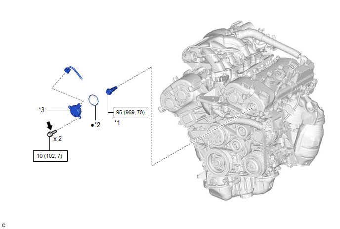
ILLUSTRATION
|
*1 | CAMSHAFT TIMING GEAR BOLT |
*2 | O-RING |
|
*3 | CAMSHAFT TIMING OIL CONTROL SOLENOID ASSEMBLY (for Exhaust Side of Bank 2) |
- | - |
|
|
N*m (kgf*cm, ft.*lbf): Specified torque |
● | Non-reusable part |
.png) |
Adhesive 1324 | ★ |
Precoated part |
READ NEXT:
 Removal
REMOVAL PROCEDURE 1. REMOVE FRONT WHEEL RH
Click here 2. REMOVE FRONT FENDER APRON SEAL RH
Click here
3. REMOVE V-BANK COVER SUB-ASSEMBLY Click here
4. REMOVE CAMSHAFT TI
Inspection
INSPECTION PROCEDURE 1. INSPECT CAMSHAFT TIMING GEAR BOLT
(a) Check the stroke of the plunger in the center of the camshaft timing gear bolt.
Standard Stroke: 2.2 mm (0.0866 in.) or more HIN
Installation
INSTALLATION PROCEDURE 1. INSTALL CAMSHAFT TIMING GEAR BOLT
(a) Make sure that the No. 1 cylinder is at TDC/compression. HINT:
Check that the cutout of the camshaft timing gear assembly is at the
SEE MORE:
Millimeter Wave Radar Sensor Communication Stop Mode
DESCRIPTION
Detection Item Symptom
Trouble Area Millimeter Wave Radar Sensor Communication Stop Mode
Any of the following conditions are met:
Communication stop for "Front Radar" is indicated on the "Communication Bus Check" screen of the Techstream.
Click here
Battery
Check the battery as follows.
■ Battery exterior
Make sure that the battery terminals are not corroded and that
there are no loose connections, cracks, or loose clamps.
Terminals
Hold-down clamp
■Before recharging
When recharging, the battery produces hydrogen gas which is flammab
© 2023-2026 Copyright www.tocamry.com
