Toyota Camry (XV70): Water Pump
Components
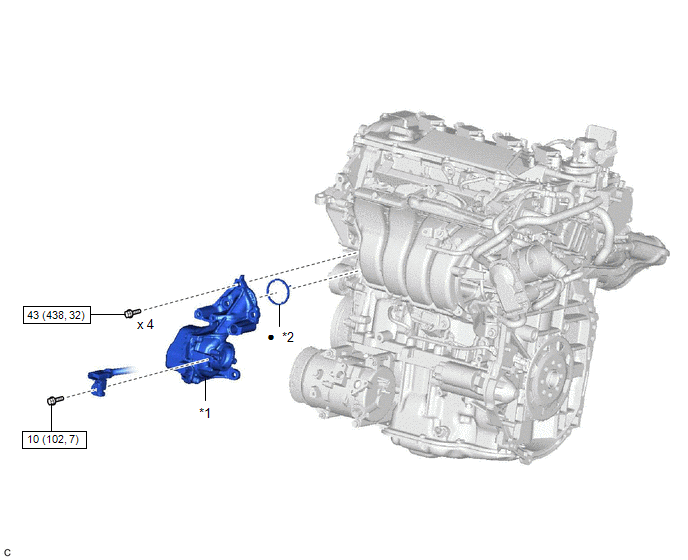
COMPONENTS
ILLUSTRATION
|
*1 | ENGINE WATER PUMP ASSEMBLY (WATER INLET HOUSING) |
*2 | GASKET |
.png) |
N*m (kgf*cm, ft.*lbf): Specified torque |
● | Non-reusable part |
Removal
REMOVAL
CAUTION / NOTICE / HINT
The necessary procedures (adjustment, calibration, initialization or registration) that must be performed after parts are removed and installed, or replaced during engine water pump assembly (water inlet housing) removal/installation are shown below.
Necessary Procedures After Parts Removed/Installed/Replaced|
Replaced Part or Performed Procedure |
Necessary Procedure | Effect/Inoperative Function when Necessary Procedure not Performed |
Link |
|---|---|---|---|
|
Battery terminal is disconnected/reconnected |
Perform steering sensor zero point calibration |
Lane Tracing Assist System |
|
|
Pre-collision system | |||
|
Memorize steering angle neutral point |
Parking assist monitor system |
| |
|
Panoramic view monitor system |
|
NOTICE:
This procedure includes the removal of small-head bolts. Refer to Small-Head Bolts of Basic Repair Hint to identify the small-head bolts.
Click here .gif)
PROCEDURE
1. REMOVE WATER INLET WITH THERMOSTAT SUB-ASSEMBLY
Click here
2. REMOVE ENGINE WATER PUMP ASSEMBLY (WATER INLET HOUSING)
| (a) Disconnect the sensor wire connector. |
|
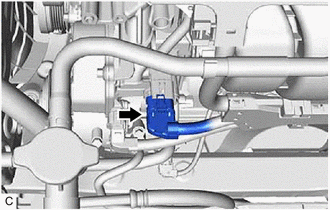
| (b) Using an 8 mm socket wrench, remove the bolt and disconnect the sensor wire from the engine water pump assembly (water inlet housing). |
|
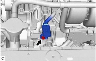
| (c) Disconnect the engine water pump assembly (water inlet housing) connector. |
|
| (d) Remove the 4 bolts and engine water pump assembly (water inlet housing) from the cylinder block assembly. |
|
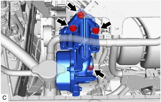
| (e) Remove the gasket from the engine water pump assembly (water inlet housing). |
|
Installation
INSTALLATION
CAUTION / NOTICE / HINT
NOTICE:
This procedure includes the installation of small-head bolts. Refer to Small-Head Bolts of Basic Repair Hint to identify the small-head bolts.
Click here .gif)
PROCEDURE
1. INSTALL ENGINE WATER PUMP ASSEMBLY (WATER INLET HOUSING)
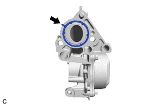
(a) Install a new gasket to the engine water pump assembly (water inlet housing).
HINT:
Be sure to clean the contact surfaces.
(b) Install the engine water pump assembly (water inlet housing) to the cylinder block assembly with the 4 bolts.
Torque:
43 N·m {438 kgf·cm, 32 ft·lbf}
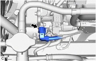
(c) Connect the engine water pump assembly (water inlet housing) connector.
| (d) Align the protrusion of the engine water pump assembly (water inlet housing) with the cutout in the sensor wire clamp. |
|

(e) Using an 8 mm socket wrench, connect the sensor wire to the engine water pump assembly (water inlet housing) with the bolt.
Torque:
10 N·m {102 kgf·cm, 7 ft·lbf}
(f) Connect the sensor wire connector.
2. INSTALL WATER INLET WITH THERMOSTAT SUB-ASSEMBLY
Click here
READ NEXT:
 Camera Heater
ComponentsCOMPONENTS ILLUSTRATION
*1 FORWARD RECOGNITION CAMERA
*2 FORWARD RECOGNITION WITH HEATER HOOD SUB-ASSEMBLY RemovalREMOVAL PROCEDURE
1. REMOVE FORWARD RECOGNITION CAM
SEE MORE:
Dtc Check / Clear
DTC CHECK / CLEAR CHECK DTC (CHECK USING TECHSTREAM)
(a) Connect the Techstream to the DLC3. (b) Turn the engine switch on (IG) and wait for 90 seconds.
(c) Turn the Techstream on. (d) Enter the following menus: Body Electrical / Navigation System / Trouble Codes. Body Electrical > Navigation
Noise Occurs
PROCEDURE
1. CHECK NOISE CONDITION
(a) Check from which direction the noise comes (front left or right, or rear left or right).
OK: The location of the noise source can be determined.
NG
GO TO STEP 3
OK
2.
CHECK SPEAKERS (a
