Toyota Camry (XV70): Wiper Motor Power Source Circuit
DESCRIPTION
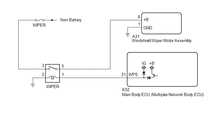
This circuit is the power source circuit for the windshield wiper motor assembly.
WIRING DIAGRAM
CAUTION / NOTICE / HINT
NOTICE:
- Inspect the fuses of circuits related to this system before performing the following procedure.
- Before replacing the main body ECU (multiplex network body ECU), refer to Registration.*
Click here
.gif)
- *: w/ Smart Key System
PROCEDURE
|
1. | READ VALUE USING TECHSTREAM |
(a) Connect the Techstream to the DLC3.
(b) Turn the ignition switch to ON.
(c) Turn the Techstream on.
(d) Enter the following menus: Body Electrical / Wiper / Data List.
(e) Read the Data List according to the display on the Techstream.
Body Electrical > Wiper > Data List|
Tester Display | Measurement Item |
Range | Normal Condition |
Diagnostic Note |
|---|---|---|---|---|
|
Motor Power Supply Voltage |
Front wiper motor assembly supply voltage status |
Min.: 0 V Max.: 63 V |
Almost the same as actual front wiper motor assembly voltage |
- |
|
Tester Display |
|---|
|
Motor Power Supply Voltage |
OK:
The Techstream display is normal.
| OK | .gif) |
PROCEED TO NEXT SUSPECTED AREA SHOWN IN PROBLEM SYMPTOMS TABLE |
|
.gif)
|
2. | CHECK HARNESS AND CONNECTOR (WINDSHIELD WIPER MOTOR ASSEMBLY - BODY GROUND) |
(a) Disconnect the A31 windshield wiper motor assembly connector.
(b) Measure the resistance according to the value(s) in the table below.
Standard Resistance:
|
Tester Connection | Condition |
Specified Condition |
|---|---|---|
|
A31-1 (GND) - Body ground |
Always | Below 1 Ω |
| NG | |
REPAIR OR REPLACE HARNESS OR CONNECTOR |
|
|
3. | CHECK HARNESS AND CONNECTOR (POWER SOURCE - WINDSHIELD WIPER MOTOR ASSEMBLY) |
(a) Measure the voltage according to the value(s) in the table below.
Standard Voltage:
|
Tester Connection | Condition |
Specified Condition |
|---|---|---|
|
A31-4 (+B) - Body ground |
Ignition switch ON |
11 to 14 V |
|
Less than approximately 60 seconds after ignition switch turned off | ||
|
Approximately 60 seconds after ignition switch turned off |
Below 1 V |
| OK | |
REPLACE WINDSHIELD WIPER MOTOR ASSEMBLY |
|
|
4. | INSPECT WIPER RELAY |
(a) Inspect the WIPER relay.
Click here
| NG | |
REPLACE WIPER RELAY |
|
|
5. | CHECK HARNESS AND CONNECTOR (POWER SOURCE - WIPER RELAY) |
(a) Measure the voltage according to the value(s) in the table below.
Standard Voltage:
|
Tester Connection | Condition |
Specified Condition |
|---|---|---|
|
3 (WIPER relay) - Body ground |
Always | 11 to 14 V |
| NG | |
REPAIR OR REPLACE HARNESS OR CONNECTOR |
|
|
6. | CHECK HARNESS AND CONNECTOR (WIPER RELAY - BODY GROUND) |
(a) Measure the resistance according to the value(s) in the table below.
Standard Resistance:
|
Tester Connection | Condition |
Specified Condition |
|---|---|---|
|
2 (WIPER relay) - Body ground |
Always | Below 1 Ω |
| NG | |
REPAIR OR REPLACE HARNESS OR CONNECTOR |
|
|
7. | CHECK HARNESS AND CONNECTOR (WIPER RELAY - WINDSHIELD WIPER MOTOR ASSEMBLY) |
(a) Measure the resistance according to the value(s) in the table below.
Standard Resistance:
|
Tester Connection | Condition |
Specified Condition |
|---|---|---|
|
5 (WIPER relay) - A31-4 (+B) |
Always | Below 1 Ω |
|
5 (WIPER relay) or A31-4 (+B) - Body ground |
Always | 10 kΩ or higher |
| NG | |
REPAIR OR REPLACE HARNESS OR CONNECTOR |
|
|
8. | CHECK HARNESS AND CONNECTOR (WIPER RELAY - MAIN BODY ECU (MULTIPLEX NETWORK BODY ECU)) |
(a) Disconnect the K52 main body ECU (multiplex network body ECU) connector.
(b) Measure the resistance according to the value(s) in the table below.
Standard Resistance:
|
Tester Connection | Condition |
Specified Condition |
|---|---|---|
|
1 (WIPER relay) - K52-21 (WPS) |
Always | Below 1 Ω |
|
1 (WIPER relay) or K52-21 (WPS) - Body ground |
Always | 10 kΩ or higher |
| OK | |
REPLACE MAIN BODY ECU (MULTIPLEX NETWORK BODY ECU)
|
| NG | |
REPAIR OR REPLACE HARNESS OR CONNECTOR |
READ NEXT:
SEE MORE:
 Disassembly
DISASSEMBLY PROCEDURE 1. REMOVE BRAKE MASTER CYLINDER STRAIGHT PIN
(a) Secure the brake master cylinder sub-assembly in a vise. NOTICE:
Place aluminum plates on the vise to prevent damage to the brake master cylinder sub-assembly.
(b) Using a 5 mm pin punch and a hammer, tap out the brake
Lost Communication with ECM/PCM "A" Missing Message (U010087,U012587,U012987,U014087,U015587)
DESCRIPTION When a malfunction is detected between various ECUs and sensors, these DTCs are stored.
DTC No. Detection Item
DTC Detection Condition Trouble Area
U010087 Lost Communication with ECM/PCM "A" Missing Message
3 seconds or more after the ignition switch to ON
