Toyota Camry (XV70): Washer Motor Circuit
DESCRIPTION
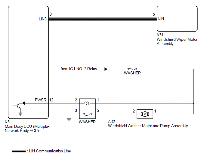
When the windshield washer motor and pump assembly receives signals from the windshield wiper switch assembly it operates to spray washer fluid from the washer nozzle sub-assemblies.
WIRING DIAGRAM
CAUTION / NOTICE / HINT
NOTICE:
- Inspect the fuses for circuits related to this system before performing the following procedure.
- Before replacing the main body ECU (multiplex network body ECU), refer to Registration.*
Click here
.gif)
- *: w/ Smart Key System
PROCEDURE
| 1. |
PERFORM ACTIVE TEST USING TECHSTREAM |
(a) Connect the Techstream to the DLC3.
(b) Turn the ignition switch to ON.
(c) Turn the Techstream on.
(d) Enter following menus: Body Electrical / Main Body / Active Test.
(e) Perform the Active Test according to the display on the Techstream.
Body Electrical > Main Body > Active Test|
Tester Display | Measurement Item |
Control Range | Diagnostic Note |
|---|---|---|---|
|
Front Washer Relay | Function to operate the windshield washer motor and pump assembly |
OFF or ON | - |
|
Tester Display |
|---|
| Front Washer Relay |
OK:
Windshield washer motor and pump assembly operates normally.
| OK | .gif) | PROCEED TO NEXT SUSPECTED AREA SHOWN IN PROBLEM SYMPTOMS TABLE |
|
.gif)
| 2. |
INSPECT WINDSHIELD WASHER MOTOR AND PUMP ASSEMBLY |
(a) Remove the windshield washer motor and pump assembly.
Click here
(b) Inspect the windshield washer motor and pump assembly.
Click here
| NG | | REPLACE WINDSHIELD WASHER MOTOR AND PUMP ASSEMBLY |
|
| 3. |
INSPECT WASHER RELAY |
(a) Inspect the WASHER relay.
Click here
| NG | | REPLACE WASHER RELAY |
|
| 4. |
CHECK HARNESS AND CONNECTOR (POWER SOURCE - WASHER RELAY) |
(a) Measure the voltage according to the value(s) in the table below.
Standard Voltage:
|
Tester Connection | Condition |
Specified Condition |
|---|---|---|
|
1 (WASHER relay) - Body ground |
Ignition switch off | Below 1 V |
|
Ignition switch ON | 11 to 14 V |
| NG | | REPAIR OR REPLACE HARNESS OR CONNECTOR |
|
| 5. |
CHECK HARNESS AND CONNECTOR (POWER SOURCE - WINDSHIELD WASHER MOTOR AND PUMP ASSEMBLY) |
(a) Measure the voltage according to the value(s) in the table below.
Standard Voltage:
|
Tester Connection | Condition |
Specified Condition |
|---|---|---|
|
A32-1 - Body ground | Ignition switch off |
Below 1 V |
|
Ignition switch ON | 11 to 14 V |
| NG | | REPAIR OR REPLACE HARNESS OR CONNECTOR |
|
| 6. |
CHECK HARNESS AND CONNECTOR (WASHER RELAY - WINDSHIELD WASHER MOTOR AND PUMP ASSEMBLY) |
(a) Measure the resistance according to the value(s) in the table below.
Standard Resistance:
|
Tester Connection | Condition |
Specified Condition |
|---|---|---|
|
5 (WASHER relay) - A32-2 |
Always | Below 1 Ω |
|
5 (WASHER relay) or A32-2 - Body ground |
Always | 10 kΩ or higher |
| NG | | REPAIR OR REPLACE HARNESS OR CONNECTOR |
|
| 7. |
CHECK HARNESS AND CONNECTOR (WASHER RELAY - BODY GROUND) |
(a) Measure the resistance according to the value(s) in the table below.
Standard Resistance:
|
Tester Connection | Condition |
Specified Condition |
|---|---|---|
|
3 (WASHER relay) - Body ground |
Always | Below 1 Ω |
| NG | | REPAIR OR REPLACE HARNESS OR CONNECTOR |
|
| 8. |
CHECK HARNESS AND CONNECTOR (WASHER RELAY - MAIN BODY ECU (MULTIPLEX NETWORK BODY ECU)) |
(a) Disconnect the K51 main body ECU (multiplex network body ECU) connector.
(b) Measure the resistance according to the value(s) in the table below.
Standard Resistance:
|
Tester Connection | Condition |
Specified Condition |
|---|---|---|
|
2 (WASHER relay) - K51-12 (FWSR) |
Always | Below 1 Ω |
|
K51-12 (FWSR) or 2 (WASHER relay) - Body ground |
Always | 10 kΩ or higher |
| OK | | REPLACE MAIN BODY ECU (MULTIPLEX NETWORK BODY ECU)
|
| NG | | REPAIR OR REPLACE HARNESS OR CONNECTOR |
READ NEXT:
SEE MORE:
 Components
COMPONENTS ILLUSTRATION
*A for TMC made
- -
*1 NO. 1 ENGINE UNDER COVER
*2 NO. 2 ENGINE UNDER COVER ASSEMBLY
*3 FRONT WHEEL OPENING EXTENSION PAD LH
*4 FRONT WHEEL OPENING EXTENSION PAD RH
*5 FRONT FENDER APRON SEAL LH
- -
Installation
INSTALLATION PROCEDURE 1. INSTALL NO. 1 FUEL TANK CUSHION
(a) Install 2 new No. 1 fuel tank cushions to the fuel tank assembly. 2. INSTALL NO. 6 FUEL TANK CUSHION
(a) Install a new No. 6 fuel tank cushion to the fuel tank assembly. 3. INSTALL FUEL TANK MAIN TUBE SUB-ASSEMBLY
(a) Engage the cla
