
Toyota Camry (XV70): Washer Fluid Level Warning Switch Circuit
DESCRIPTION
When the washer fluid level is lower than a certain level, a warning message is displayed on the combination meter assembly.
WIRING DIAGRAM
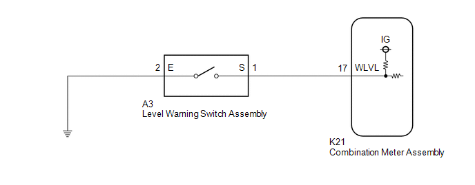
PROCEDURE
| 1. |
READ VALUE USING TECHSTREAM |
(a) Connect the Techstream to the DLC3.
(b) Turn the ignition switch ON.
(c) Turn the Techstream on.
(d) Enter the following menus: Body Electrical / Combination Meter / Data List.
(e) Read the Data List according to the display on the Techstream.
Body Electrical > Combination Meter > Data List|
Tester Display | Measurement Item |
Range | Normal Condition |
Diagnostic Note |
|---|---|---|---|---|
|
Washer Level Warning Switch |
Washer fluid level warning switch |
OFF or ON | OFF: Washer fluid level not low ON: Washer fluid level low |
- |
|
Tester Display |
|---|
| Washer Level Warning Switch |
OK:
The Techstream display changes correctly in response to the washer fluid level.
| OK | .gif) | REPLACE COMBINATION METER ASSEMBLY
|
|
.gif)
| 2. |
INSPECT LEVEL WARNING SWITCH ASSEMBLY |
(a) Remove the level warning switch assembly.
Click here
.gif)
(b) Inspect the level warning switch assembly.
Click here
| NG | | REPLACE LEVEL WARNING SWITCH ASSEMBLY
|
|
| 3. |
CHECK HARNESS AND CONNECTOR (LEVEL WARNING SWITCH ASSEMBLY - COMBINATION METER ASSEMBLY) |
(a) Disconnect the K21 combination meter assembly connector.
(b) Measure the resistance according to the value(s) in the table below.
Standard Resistance:
|
Tester Connection | Condition |
Specified Condition |
|---|---|---|
|
A3-1 (S) - K21-17 (WLVL) |
Always | Below 1 Ω |
|
A3-1 (S) or K21-17 (WLVL) - Body ground |
Always | 10 kΩ or higher |
| NG | | REPAIR OR REPLACE HARNESS OR CONNECTOR |
|
| 4. |
CHECK HARNESS AND CONNECTOR (LEVEL WARNING SWITCH ASSEMBLY - BODY GROUND) |
(a) Measure the resistance according to the value(s) in the table below.
Standard Resistance:
|
Tester Connection | Condition |
Specified Condition |
|---|---|---|
|
A3-2 (E) - Body ground |
Always | Below 1 Ω |
| OK | | REPLACE COMBINATION METER ASSEMBLY
|
| NG | | REPAIR OR REPLACE HARNESS OR CONNECTOR |
READ NEXT:
 Components
COMPONENTS ILLUSTRATION
*1 LOWER STEERING COLUMN COVER SUB-ASSEMBLY
*2 UPPER STEERING COLUMN COVER
*3 WINDSHIELD WIPER SWITCH ASSEMBLY
- -
Removal
REMOVAL PROCEDURE 1. REMOVE LOWER STEERING COLUMN COVER SUB-ASSEMBLY
NOTICE: Removing the lower steering column cover sub-assembly in the incorrect order will cause the parts to break.
(a) Release
SEE MORE:
Removal
REMOVAL CAUTION / NOTICE / HINT
The necessary procedures (adjustment, calibration, initialization, or registration) that must be performed after parts are removed and installed, or replaced during engine unit removal/installation are shown below. Necessary Procedure After Parts Removed/Installed/R
Control Module Communication Bus "B" Off Bus Off (U007488,...,U015187)
DESCRIPTION The skid control ECU (brake actuator assembly) communicates with the following ECUs and sensors via CAN communication.
ECM
TCM (ECM)
Yaw rate and acceleration sensor (airbag sensor assembly)
Steering angle sensor
Power steering ECU (rack and pinion power steering gea
