Toyota Camry (XV70): Adjustment
ADJUSTMENT
CAUTION / NOTICE / HINT

|
*a | Centering Bolt |
|
*b | Standard Bolt |
HINT:
- Centering bolts are used to mount the door hinge to the door. The door cannot be adjusted with the centering bolts installed. Substitute the centering bolts with standard bolts when making adjustments.
- Specified torque for standard bolts is shown in the standard bolt chart.
Click here
.gif)
PROCEDURE
1. INSPECT LUGGAGE COMPARTMENT DOOR
(a) Check that the clearance measurements of areas a through d are within each standard range.
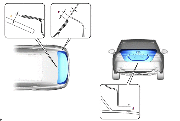 Standard Clearance
 |
Area | Measurement |
Area | Measurement |
|---|---|---|---|
|
a | 5.8 mm (0.228 in.) |
b | 2.6 to 5.6 mm (0.102 to 0.220 in.) |
|
c | -1.4 to 1.6 mm (-0.0551 to 0.063 in.) |
d | 4.0 to 8.0 mm (0.157 to 0.315 in.) |
2. REMOVE SPARE WHEEL COVER ASSEMBLY
Click here
3. REMOVE SPARE WHEEL COVER TRAY
Click here
4. REMOVE REAR FLOOR FINISH PLATE
Click here
5. REMOVE LUGGAGE COMPARTMENT DOOR COVER
Click here
6. REMOVE LUGGAGE COMPARTMENT DOOR HINGE COVER LH
Click here
7. REMOVE LUGGAGE COMPARTMENT DOOR HINGE COVER RH
Click here
8. ADJUST LUGGAGE COMPARTMENT DOOR
| (a) Loosen the 4 door side hinge bolts to adjust the door horizontally and vertically. |
|
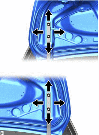
(b) Tighten the 4 bolts after adjustment.
Torque:
7.5 N
READ NEXT:
 Reassembly
REASSEMBLY PROCEDURE 1. INSTALL REAR SPOILER RETAINER (w/ Rear Spoiler)
except TRD: Click here
2. INSTALL REAR SPOILER (w/ Rear Spoiler) Click here
3. INSTALL LUGGAGE COMPARTMENT DOOR CUS
Components
COMPONENTS ILLUSTRATION
*1 COWL SIDE TRIM SUB-ASSEMBLY LH
*2 FRONT DOOR OPENING TRIM WEATHERSTRIP LH
*3 FRONT DOOR SCUFF PLATE LH
*4 HOOD LOCK CONTROL LEVER
SEE MORE:
Components
COMPONENTS ILLUSTRATION
*1 COOL AIR INTAKE DUCT SEAL
*2 COWL SIDE TRIM SUB-ASSEMBLY LH
*3 FRONT DOOR SCUFF PLATE LH
*4 FRONT FENDER LINER LH
*5 FRONT WHEEL OPENING EXTENSION PAD LH
*6 HOOD LOCK ASSEMBLY
*7 HOOD LOCK CONTROL C
Tire pressure warning system
Your vehicle is equipped with a tire pressure warning system that uses
tire pressure warning valve and transmitters to detect low tire inflation
pressure before serious problems arise.
Vehicles without a tire inflation pressure display function
If the tire pressure drops below a predetermined le
