
Toyota Camry (XV70): Components
COMPONENTS
ILLUSTRATION
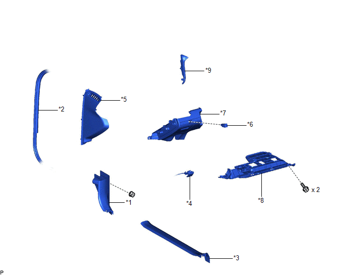
|
*1 | COWL SIDE TRIM SUB-ASSEMBLY LH |
*2 | FRONT DOOR OPENING TRIM WEATHERSTRIP LH |
|
*3 | FRONT DOOR SCUFF PLATE LH |
*4 | HOOD LOCK CONTROL LEVER SUB-ASSEMBLY |
|
*5 | INSTRUMENT SIDE PANEL LH |
*6 | LUGGAGE COMPARTMENT DOOR OPENING SWITCH ASSEMBLY |
|
*7 | NO. 1 INSTRUMENT PANEL SUB-ASSEMBLY |
*8 | NO. 1 INSTRUMENT PANEL UNDER COVER SUB-ASSEMBLY |
|
*9 | NO. 2 METER HOOD CLUSTER |
- | - |
READ NEXT:
 Removal
REMOVAL PROCEDURE 1. REMOVE FRONT DOOR SCUFF PLATE LH
Click here
2. REMOVE COWL SIDE TRIM SUB-ASSEMBLY LH
Click here
3. DISCONNECT FRONT DOOR
Inspection
INSPECTION PROCEDURE 1. INSPECT LUGGAGE COMPARTMENT DOOR OPENING SWITCH ASSEMBLY
(a) Check the switch. (1) Measure the resistance according to the value(s) in the table below.
Standard Resi
Installation
INSTALLATION PROCEDURE 1. INSTALL LUGGAGE COMPARTMENT DOOR OPENING SWITCH ASSEMBLY
(a) Engage the 2 claws to install the luggage compartment door opening switch assembly as shown in the illustratio
SEE MORE:
Compressor Lock (B1422)
DESCRIPTION The ECM sends the engine speed signal to the air conditioning amplifier assembly via CAN communication.
The air conditioning amplifier assembly reads the difference between compressor speed and engine speed. If the difference becomes excessively large, the air conditioning amplifier ass
Customization
Customizable features
Your vehicle includes a variety of electronic features that can be
personalized to suit your preferences. The settings of these features
can be changed using the multi-information display, on the
audio system screen, or at your Toyota dealer.
Customizing vehicle features
© 2023-2026 Copyright www.tocamry.com
