Toyota Camry (XV70): Adjustment
ADJUSTMENT
CAUTION / NOTICE / HINT
.png)
|
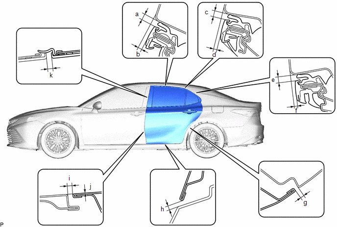
*a | Centering Bolt |
|
*b | Standard Bolt |
HINT:
- Use the same procedure for the RH side and LH side.
- The following procedure is for the LH side.
- Centering bolts are used to install the door hinges to the vehicle body and door. The door cannot be adjusted with the centering bolts installed. Substitute the centering bolts with standard bolts when making adjustments.
- The specified torque for standard bolts is shown in the standard bolt chart.
Click here
.gif)
PROCEDURE
1. INSPECT REAR DOOR
(a) Check that the clearance measurements of areas a through k are within each standard range.
 Standard Clearance
 |
Area | Measurement |
Area | Measurement |
|---|---|---|---|
|
a | 3.3 to 6.7 mm (0.130 to 0.264 in.) |
b | 1.2 to 5.2 mm (0.0472 to 0.205 in.) |
|
c | 3.3 to 6.7 mm (0.130 to 0.264 in.) |
d | 0.6 to 4.6 mm (0.0236 to 0.181 in.) |
|
e | 3.3 to 6.7 mm (0.130 to 0.264 in.) |
f | 0.6 to 4.6 mm (0.0236 to 0.181 in.) |
|
g | 2.3 to 5.3 mm (0.0906 to 0.209 in.) |
h | 5.3 mm (0.209 in.) |
|
i | 4.1 mm (0.161 in.) |
j | 0 mm (0 in.) |
|
k | 2.3 to 6.3 mm (0.0906 to 0.248 in.) |
- | - |
2. ADJUST REAR DOOR
NOTICE:
Make sure to turn the ignition switch off before adjusting the door lock strikers.
| (a) Using SST, loosen the 4 hinge bolts on the vehicle body and adjust the door position. SST: 09812-00020 |
|
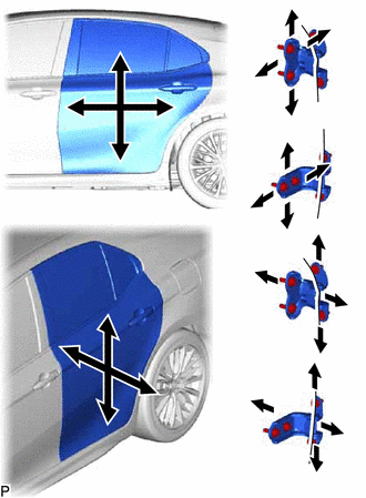
(b) Tighten the 4 hinge bolts on the vehicle body after adjustment.
Torque:
26 N
READ NEXT:
 Reassembly
REASSEMBLY CAUTION / NOTICE / HINT
HINT:
Use the same procedure for the RH side and LH side.
The following procedure is for the LH side.
PROCEDURE 1. INSTALL REAR DOOR WINDOW FRAME
Rear Door Opening Trim Weatherstrip
ComponentsCOMPONENTS ILLUSTRATION
*1 REAR DOOR OPENING TRIM WEATHERSTRIP
*2 REAR DOOR SCUFF PLATE RemovalREMOVAL CAUTION / NOTICE / HINT
HINT:
Use the same procedur
SEE MORE:
Installation
INSTALLATION PROCEDURE 1. INSTALL REAR STABILIZER BUSHING
(a) Install the 2 rear stabilizer bushings to the rear stabilizer bar.
NOTICE: Be sure to install the rear stabilizer bushings so that each cutout faces the front of the vehicle.
2. INSTALL REAR NO. 1 STABILIZER BAR BRACKET (a) Install
Operation Check
OPERATION CHECK AUTOMATIC LIGHT CONTROL SYSTEM OPERATION CHECK
NOTICE: Make sure that the customize settings are set to default when performing the automatic light control system operation check.
Click here (a) Turn the ignition switch to ON.
(b) Turn the light control switch to the AUTO
