
Toyota Camry (XV70): Air Conditioning Amplifier
Components
COMPONENTS
ILLUSTRATION
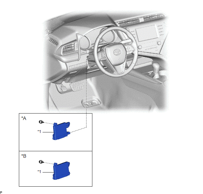
|
*A | w/o Seat Heater |
*B | w/ Seat Heater |
|
*1 | AIR CONDITIONING AMPLIFIER ASSEMBLY |
- | - |
Removal
REMOVAL
PROCEDURE
1. REMOVE ACCELERATOR PEDAL
for A25A-FKS:
Click here

for 2GR-FKS:
Click here
2. REMOVE AIR CONDITIONING AMPLIFIER ASSEMBLY
| (a) Disengage each clamp. |
|
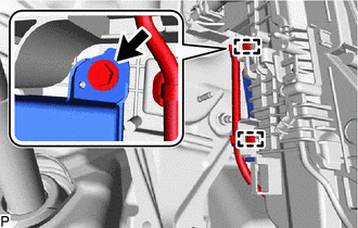
(b) Remove the screw.
(c) Disengage the guide as shown in the illustration.
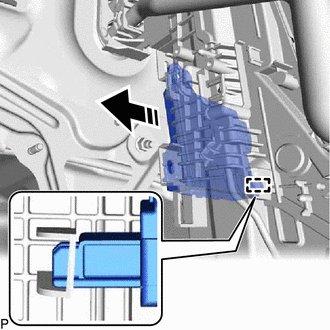
 |
Remove in this Direction |
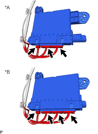
| (d) Disconnect each connector to remove the air conditioning amplifier assembly. |
|
Installation
INSTALLATION
PROCEDURE
1. INSTALL AIR CONDITIONING AMPLIFIER ASSEMBLY
(a) Connect each connector.
(b) Align the lower part of the air conditioning amplifier assembly with the rib of the air conditioner unit assembly and engage the guide as shown in the illustration.
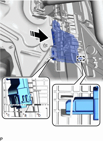
|
*a | Lower Part of Air Conditioning Amplifier Assembly |
|
*b | Rib of Air Conditioner Unit Assembly |
|
*c | Align |
 |
Install in this Direction |
| (c) Move the air conditioning amplifier assembly in each direction shown in the illustration to check that the guide is securely engaged. |
|
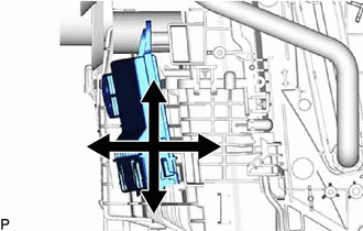
(d) Install the air conditioning amplifier assembly with the screw.
(e) Engage each clamp.
2. INSTALL ACCELERATOR PEDAL
for A25A-FKS:
Click here

for 2GR-FKS:
Click here
READ NEXT:
 Air Conditioning Filter
ComponentsCOMPONENTS ILLUSTRATION
*1 CLEAN AIR FILTER
*2 AIR FILTER COVER PLATE
*3 LOWER INSTRUMENT COVER LH
*4 AIR FILTER CASE
*5 AIR FILTER SUB-ASSEMBLY
Air Conditioning Panel
ComponentsCOMPONENTS ILLUSTRATION
*1 AIR CONDITIONING CONTROL ASSEMBLY
*2 NO. 1 METER HOOD CLUSTER
*3 NO. 2 INSTRUMENT PANEL GARNISH SUB-ASSEMBLY
*4 NO. 3 INSTRUMENT PA
SEE MORE:
Eco-friendly driving information
■ Fuel consumption
Current fuel consumption
Displays the instantaneous current
fuel consumption.
Average fuel economy (after
start)
Displays the average fuel consumption
since engine start.*1
Driving range
Displays the driving range with remaining fuel.*2, 3
Gadget*4
The fo
Components
COMPONENTS ILLUSTRATION
*1 FLOW SHUTTING VALVE (WATER BY-PASS HOSE ASSEMBLY)
*2 VACUUM HOSE
*3 ENGINE WIRE HARNESS
*4 OUTLET HEATER HOSE
*5 INLET HEATER HOSE
*6 NO. 2 WATER BY-PASS PIPE SUB-ASSEMBLY
*7 WATER HOSE CLAMP BRACKET
-
