Toyota Camry (XV70): Components
COMPONENTS
ILLUSTRATION
|
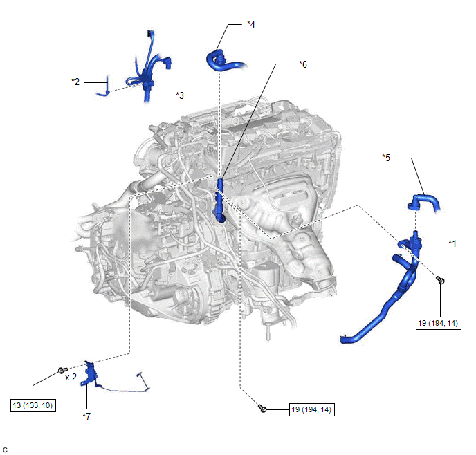
*1 | FLOW SHUTTING VALVE (WATER BY-PASS HOSE ASSEMBLY) |
*2 | VACUUM HOSE |
|
*3 | ENGINE WIRE HARNESS |
*4 | OUTLET HEATER HOSE |
|
*5 | INLET HEATER HOSE |
*6 | NO. 2 WATER BY-PASS PIPE SUB-ASSEMBLY |
|
*7 | WATER HOSE CLAMP BRACKET |
- | - |
.png) |
N*m (kgf*cm, ft.*lbf): Specified torque |
- | - |
READ NEXT:
 Removal
REMOVAL CAUTION / NOTICE / HINT
The necessary procedures (adjustment, calibration, initialization or registration) that must be performed after parts are removed and installed, or replaced during fl
Inspection
INSPECTION PROCEDURE 1. INSPECT FLOW SHUTTING VALVE (WATER BY-PASS HOSE ASSEMBLY)
(a) Measure the resistance according to the value(s) in the table below.
Standard Resistance:
Tester
Installation
INSTALLATION PROCEDURE 1. INSTALL FLOW SHUTTING VALVE (WATER BY-PASS HOSE ASSEMBLY)
(a) Connect the flow shutting valve (water by-pass hose assembly) to the transmission oil cooler and slide the cli
SEE MORE:
On-vehicle Inspection
ON-VEHICLE INSPECTION PROCEDURE
1. INSPECT COOLING FAN SYSTEM CAUTION: To prevent injury due to contact with an operating cooling fan, keep your hands and clothing away from the cooling fan when inspecting the cooling fan system.
(a) Connect the Techstream to the DLC3.
(b) Turn the ignition s
Rear Door RH ECU Communication Stop (B2323)
DESCRIPTION This DTC is stored when LIN communication between the power window regulator motor assembly (for rear door RH) and main body ECU (multiplex network body ECU) stops for 10 seconds or more.
DTC No. Detection Item
DTC Detection Condition Trouble Area
B2323 Rear Door
© 2023-2026 Copyright www.tocamry.com
