Toyota Camry (XV70): Removal
REMOVAL
CAUTION / NOTICE / HINT
The necessary procedures (adjustment, calibration, initialization or registration) that must be performed after parts are removed and installed, or replaced during flow shutting valve (water by-pass hose assembly) removal/installation are shown below.
Necessary Procedures After Parts Removed/Installed/Replaced|
Replaced Part or Performed Procedure |
Necessary Procedure | Effect/Inoperative Function when Necessary Procedure not Performed |
Link |
|---|---|---|---|
|
Battery terminal is disconnected/reconnected |
Perform steering sensor zero point calibration |
Lane Tracing Assist System |
|
|
Pre-collision system | |||
|
Memorize steering angle neutral point |
Parking assist monitor system |
| |
|
Panoramic view monitor system |
| ||
|
Replacement of ECM | Vehicle Identification Number (VIN) registration |
MIL comes on |
|
|
ECU communication ID registration (Immobiliser system) |
Engine start function |
| |
|
Replacement of ECM (If possible, read the transaxle compensation code from the previous ECM) |
|
|
|
|
Replacement of ECM (If impossible, read the transaxle compensation code from the previous ECM) |
| ||
| Replacement of ECM*1 |
Code registration |
|
|
|
Replacement of ECM*2 | Code registration |
|
|
- *1: w/ Smart Key System
- *2: w/o Smart Key System
- *3: When the ECM is replaced with a new one, reset memory is unnecessary.
PROCEDURE
1. REMOVE FLOW SHUTTING VALVE (NO. 1 WATER BY-PASS HOSE)
Click here .gif)
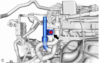
2. REMOVE FLOW SHUTTING VALVE (WATER BY-PASS HOSE ASSEMBLY)
| (a) Disengage the clamp to disconnect the vacuum hose from the engine wire harness. |
|
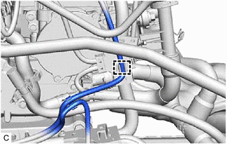
| (b) Disconnect the 3 connectors. |
|
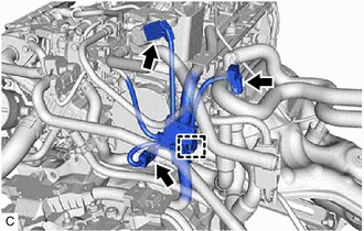
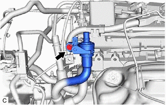
(c) Disengage the clamp to disconnect the engine wire harness from the water hose clamp bracket.
(d) Disconnect the outlet heater hose connector from the No. 2 water by-pass pipe sub-assembly.
NOTICE:
Remove any foreign matter on the No. 2 water by-pass pipe sub-assembly and outlet heater hose connector before performing this work.
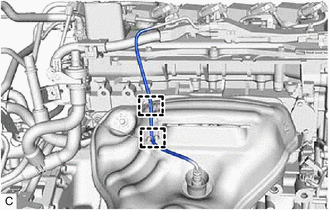
(1) Pull out the retainer to disengage the lock claws and pull off the outlet heater hose connector.
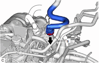
|
*a | Retainer |
.png) |
Pull out |
.png) |
Pull off |
(2) Check that there is no foreign matter on the sealing surfaces of the disconnected water lines. Clean them if necessary.
(3) Cover the disconnected No. 2 water by-pass pipe sub-assembly and outlet heater hose connector with plastic bags to prevent damage and contamination.
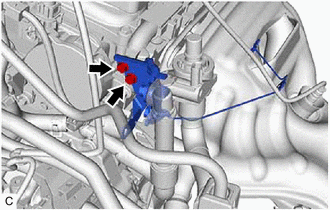
(e) Disconnect the inlet heater hose connector from the flow shutting valve (water by-pass hose assembly).
NOTICE:
Remove any foreign matter on the flow shutting valve (water by-pass hose assembly) and inlet heater hose connector before performing this work.
(1) Pull out the retainer to disengage the lock claws and pull off the inlet heater hose connector.
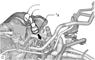
|
*a | Retainer |
|
|
Pull out |
|
|
Pull off |
(2) Check that there is no foreign matter on the sealing surfaces of the disconnected water lines. Clean them if necessary.
(3) Cover the disconnected inlet heater hose connector with plastic bag to prevent damage and contamination.
| (f) Remove the bolt to disconnect the No. 2 water by-pass pipe sub-assembly. |
|
| (g) Remove the bolt to disconnect the flow shutting valve (water by-pass hose assembly). |
|
| (h) Disengage the 2 clamps to disconnect the wire harness. |
|
| (i) Remove the 2 bolts and the water hose clamp bracket. |
|
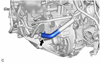
| (j) Slide the clip and disconnect the flow shutting valve (water by-pass hose assembly) from the water by-pass outlet sub-assembly. HINT: Use a container to catch any engine coolant which flows out of the flow shutting valve (water by-pass hose assembly) and water by-pass outlet sub-assembly. |
|

| (k) Slide the clip and disconnect the flow shutting valve (water by-pass hose assembly) from the transmission oil cooler. HINT: Use a container to catch any engine coolant which flows out of the flow shutting valve (water by-pass hose assembly) and transmission oil cooler. |
|
READ NEXT:
 Inspection
INSPECTION PROCEDURE 1. INSPECT FLOW SHUTTING VALVE (WATER BY-PASS HOSE ASSEMBLY)
(a) Measure the resistance according to the value(s) in the table below.
Standard Resistance:
Tester
Installation
INSTALLATION PROCEDURE 1. INSTALL FLOW SHUTTING VALVE (WATER BY-PASS HOSE ASSEMBLY)
(a) Connect the flow shutting valve (water by-pass hose assembly) to the transmission oil cooler and slide the cli
SEE MORE:
Removal
REMOVAL CAUTION / NOTICE / HINT
The necessary procedures (adjustment, calibration, initialization, or registration) that must be performed after parts are removed and installed, or replaced during oil pump removal/installation are shown below. Necessary Procedure After Parts Removed/Installed/Repl
Speed Signal Malfunction (B15C2)
DESCRIPTION The navigation ECU receives a vehicle speed signal from the combination meter assembly and information from the navigation antenna assembly, and then adjusts the vehicle position on the map.
The navigation ECU stores this DTC when the difference between the speed information that the n
