
Toyota Camry (XV70): Air Outlet Damper Control Servo Motor Circuit (B1443)
DESCRIPTION
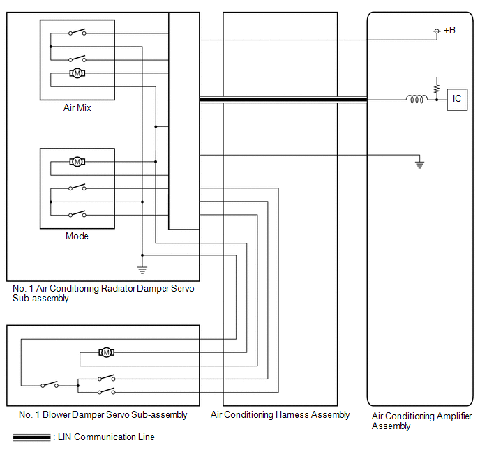
The No. 1 air conditioning radiator damper servo sub-assembly (mode) sends pulse signals to inform the air conditioning amplifier assembly of the damper position. The air conditioning amplifier assembly activates the motor (normal or reverse) based on these signals to move the air outlet damper to the appropriate position, which controls the air outlet switching.
The air conditioning amplifier assembly communicates with the servo through a communication/driver IC and wiring assembly called the air conditioning harness assembly.
|
DTC No. | Detection Item |
DTC Detection Condition | Trouble Area |
Memory |
|---|---|---|---|---|
| B1443 |
Air Outlet Damper Control Servo Motor Circuit |
Air outlet damper position sensor value does not change even if air conditioning amplifier assembly operates No. 1 air conditioning radiator damper servo sub-assembly (mode) |
| Memorized (30 sec. or more)* |
- *: The air conditioning amplifier assembly stores this DTC if the malfunction has occurred for the period of time indicated in the brackets.
|
Vehicle Condition | |||
|---|---|---|---|
|
Pattern 1 | Pattern 2 | ||
|
Diagnosis Condition | No. 1 air conditioning radiator damper servo sub-assembly (mode) operating |
0 | 0 |
|
Malfunction | Air outlet damper servo operation request signals are output but the air outlet damper position sensor value does not change |
0 | - |
|
Air outlet damper servo operation request signals are output but the air outlet damper position sensor value is abnormal |
- | 0 | |
|
Detection Time | Continuously for 30 seconds or more |
Continuously for 30 seconds or more | |
|
Trip Count | 1 trip |
1 trip | |
HINT:
If the conditions of either of these patterns are detected, a DTC will be stored.
WIRING DIAGRAM
CAUTION / NOTICE / HINT
HINT:
- Confirm that no mechanical problems are present because this DTC can be stored when either a damper link or damper is mechanically locked.
- When installing a damper servo motor, make sure to install it correctly.
Click here
.gif)
- After replacing a damper servo motor, make sure to perform Servo Motor Initialization.
Click here
PROCEDURE
|
1. | CHECK FOR DTC |
(a) Check for DTCs.
Body Electrical > Air Conditioner > Trouble Codes|
Result | Proceed to |
|---|---|
|
Only DTC B1497 is output |
A |
| DTC B1441, B1442 and B1443 are output |
B |
| Only DTC B1443 is output |
C |
| A |
.gif) | GO TO DTC B1497
|
| B |
| REPLACE NO. 1 AIR CONDITIONING RADIATOR DAMPER SERVO SUB-ASSEMBLY
|
|
.gif)
| 2. |
INSPECT NO. 1 AIR CONDITIONING RADIATOR DAMPER SERVO SUB-ASSEMBLY (INSTALLATION CONDITION) |
(a) Check that the No. 1 air conditioning radiator damper servo sub-assembly is installed correctly.
Click here
OK:
The No. 1 air conditioning radiator damper servo sub-assembly is installed correctly.
| NG | | INSTALL NO. 1 AIR CONDITIONING RADIATOR DAMPER SERVO SUB-ASSEMBLY CORRECTLY |
|
| 3. |
INSPECT NO. 1 AIR CONDITIONING RADIATOR DAMPER SERVO SUB-ASSEMBLY (MOTOR, LINK, DAMPER) |
(a) Check for a wire harness caught between the links of the motors and dampers.
OK:
No wire harnesses are caught between the links of the motors and dampers.
| NG | | REMOVE PINCHED WIRE HARNESS |
|
| 4. |
INSPECT AIR CONDITIONING RADIATOR ASSEMBLY (DAMPER) |
(a) Remove the No. 1 air conditioning radiator damper servo sub-assembly.
Click here
(b) Operate the dampers by hand.
OK:
The dampers are easily operated by hand.
| OK | | REPLACE NO. 1 AIR CONDITIONING RADIATOR DAMPER SERVO SUB-ASSEMBLY
|
| NG | | REPLACE AIR CONDITIONING RADIATOR ASSEMBLY
|
READ NEXT:
 Compressor Solenoid Circuit (B1451)
DESCRIPTION In this circuit, the compressor assembly with pulley (compressor solenoid) receives refrigerant compression demand signals from the air conditioning amplifier assembly.
Based on this sign
Communication Malfunction (Bus Ic) (B1497)
DESCRIPTION The air conditioning harness assembly connects the air conditioning amplifier assembly and the servo motors. The air conditioning amplifier assembly supplies power and sends operation inst
Lost Communication with Front Panel LIN (B14B2)
DESCRIPTION The air conditioning control assembly communicates with the air conditioning amplifier assembly via LIN communication.
If a malfunction occurs in the LIN communication system, the air con
SEE MORE:
On-vehicle Inspection
ON-VEHICLE INSPECTION CAUTION / NOTICE / HINT
NOTICE:
Do not remove the generator pulley cap.
If the generator pulley cap is removed, replace the generator pulley cap and generator pulley with clutch with new ones as the correct grease amount cannot be confirmed.
HINT: If it is confir
Air Conditioning Panel
ComponentsCOMPONENTS ILLUSTRATION
*1 AIR CONDITIONING CONTROL ASSEMBLY
*2 NO. 1 METER HOOD CLUSTER
*3 NO. 2 INSTRUMENT PANEL GARNISH SUB-ASSEMBLY
*4 NO. 3 INSTRUMENT PANEL REGISTER ASSEMBLY RemovalREMOVAL PROCEDURE
1. REMOVE NO. 1 METER HOOD CLUSTER Click here
