Toyota Camry (XV70): On-vehicle Inspection
Toyota Camry Repair Manual XV70 (2018-2024) / Power Source, Network / 2gr-fks (battery / Charging) / Generator / On-vehicle Inspection
ON-VEHICLE INSPECTION
CAUTION / NOTICE / HINT
NOTICE:
- Do not remove the generator pulley cap.
- If the generator pulley cap is removed, replace the generator pulley cap and generator pulley with clutch with new ones as the correct grease amount cannot be confirmed.
HINT:
If it is confirmed that the generator assembly is not generating power, it is not necessary to perform the counterclockwise check as another malfunction is suspected.
PROCEDURE
1. REMOVE V-RIBBED BELT
Click here
.gif)
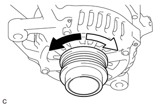
2. INSPECT GENERATOR PULLEY WITH CLUTCH
(a) Check that the generator pulley with clutch operates in accordance with the following table.
 |
Counterclockwise |
 |
Clockwise |
Standard:
|
Counterclockwise | Clockwise |
|---|---|
|
Spins Freely | Lock |
HINT:
If the generator pulley with clutch does not turn smoothly, does not operate as specified, or an abnormal sound is output, replace it with a new one.
3. INSTALL V-RIBBED BELT
Click here
READ NEXT:
 Removal
REMOVAL CAUTION / NOTICE / HINT
The necessary procedures (adjustment, calibration, initialization or registration) that must be performed after parts are removed and installed, or replaced generator
Disassembly
DISASSEMBLY PROCEDURE 1. REMOVE GENERATOR PULLEY CAP
(a) Using a screwdriver, remove the generator pulley cap from the generator pulley with clutch.
NOTICE:
Do not reuse the generator p
Inspection
INSPECTION PROCEDURE 1. INSPECT GENERATOR BRUSH HOLDER ASSEMBLY
(a) Using a vernier caliper, measure the length of the exposed brushes.
Standard Exposed Brush Length: 9.5 to 11.5 mm (0.374 t
SEE MORE:
Inspection
INSPECTION CAUTION / NOTICE / HINT
NOTICE:
When using a vise, place aluminum plates between the part and vise.
When using a vise, do not overtighten it.
PROCEDURE 1. INSPECT REAR DRIVE SHAFT ASSEMBLY
(a) Check that there is no excessive play in the radial direction of the outboar
Bank 1 Air-Fuel Ratio Imbalance (Port) (P11EA00,...,P21A100)
DESCRIPTION Refer to DTC P030000. Click here
Refer to DTC P219519. Click here
DTC No. Detection Item
DTC Detection Condition Trouble Area
MIL Memory
Note P11EA00
Bank 1 Air-Fuel Ratio Imbalance (Port)
The difference in air fuel ratios between the cy
© 2023-2026 Copyright www.tocamry.com
