Toyota Camry (XV70): Brake Hold Standby Indicator Light Circuit
DESCRIPTION
The brake hold standby indicator light turns on if brake hold control is possible when the following conditions required for operation standby are met and the brake hold switch (electric parking brake switch assembly) is pressed while the ignition switch on.
- Conditions required for operation standby:
- The driver door is closed.
- The driver seat belt is fastened.
- The system is normal.
HINT:
If a malfunction occurs in one of the following systems, the brake hold operated indicator light will blink. If this occurs, perform troubleshooting on the malfunctioning system.
- Brake system
- Electric parking brake system
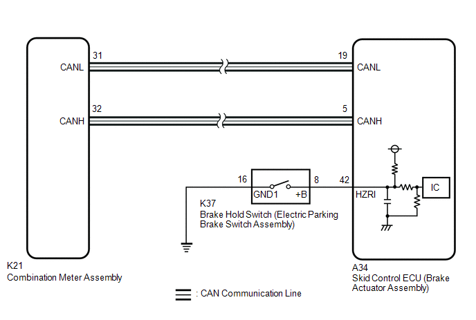
WIRING DIAGRAM
CAUTION / NOTICE / HINT
NOTICE:
After replacing the skid control ECU (brake actuator assembly), perform acceleration sensor zero point calibration and system information memorization.
Click here .gif)
PROCEDURE
| 1. |
PRE-CHECK |
(a) If the brake hold standby indicator light does not illuminate even though the brake hold switch (electric parking brake switch assembly) is pushed, check that the brake hold function operation conditions are met.
- The driver door is closed.
- The driver seat belt is fastened.
- The system is normal.
HINT:
If a malfunction occurs in one of the following systems, the brake hold operated indicator light will blink. If this occurs, perform troubleshooting on the malfunctioning system.
- Brake system
- Electric parking brake system
|
.gif)
| 2. |
READ VALUE USING TECHSTREAM (BRAKE HOLD READY) |
(a) Connect the Techstream to the DLC3.
(b) Turn the ignition switch to ON.
(c) Enter the following menus: Chassis / Brake/EPB / Data List.
Chassis > Brake > Data List|
Tester Display | Measurement Item |
Range | Normal Condition |
Diagnostic Note |
|---|---|---|---|---|
|
Brake Hold Ready | Brake hold control permission status |
Not in stand-by mode / Stand-by mode |
Not in stand-by mode: Brake hold function not operating (brake hold indicator not illuminated) Stand-by mode: Brake hold function stand-by state (brake hold indicator illuminated) |
- |
|
Tester Display |
|---|
| Brake Hold Ready |
(d) All of the following brake hold operation conditions are met:
- The driver door is closed.
- The driver seat belt is fastened.
(e) Check the brake hold standby indicator light and mode condition on the Techstream changes according to brake hold switch (electric parking brake switch assembly) operation.
Standard:
|
Brake Hold Switch (Electric Parking Brake Switch Assembly) Operation |
Mode Condition Display | Brake Hold Standby Indicator Light |
|---|---|---|
|
Not pressed | Not in stand-by mode |
Does not come on |
|
Pressing the brake hold switch (electric parking brake switch assembly) |
Stand-by mode | come on |
|
Result | Proceed to |
|---|---|
|
Indicator light and mode condition display do not change |
A |
| Mode condition display is normal, but indicator light does not change |
B |
| Indicator light and mode condition display are normal |
C |
| B |
.gif) | INSPECT METER / GAUGE SYSTEM |
| C |
| USE SIMULATION METHOD TO CHECK
|
|
| 3. |
INSPECT ELECTRIC PARKING BRAKE SWITCH ASSEMBLY |
(a) Inspect the brake hold switch (electric parking brake switch assembly).
Click here
OK:
The brake hold switch (electric parking brake switch assembly) is normal.
| NG | | REPLACE ELECTRIC PARKING BRAKE SWITCH ASSEMBLY |
|
| 4. |
CHECK HARNESS AND CONNECTOR (ELECTRIC PARKING BRAKE SWITCH ASSEMBLY - BRAKE ACTUATOR ASSEMBLY) |
(a) Make sure that there is no looseness at the locking part and the connecting part of the connector.
OK:
The connector is securely connected.
(b) Disconnect the A34 skid control ECU (brake actuator assembly) connector.
(c) Disconnect the K37 brake hold switch (electric parking brake switch assembly) connector.
(d) Check both the connector case and the terminal for deformation and corrosion.
OK:
No deformation or corrosion.
(e) Measure the resistance according to the value(s) in the table below.
Standard Resistance:
|
Tester Connection | Condition |
Specified Condition |
|---|---|---|
|
K37-8 (+B) - A34-42 (HZRI) |
Always | Below 1 Ω |
|
K37-8 (+B) or A34-42 (HZRI) - Body ground |
Always | 10 kΩ or higher |
|
K37-16 (GND1) - Body ground |
1 minute or more after disconnecting the cable from the negative (-) battery terminal |
Below 1 Ω |
| OK | | REPLACE BRAKE ACTUATOR ASSEMBLY |
| NG | | REPAIR OR REPLACE HARNESS OR CONNECTOR |
READ NEXT:
 Brake Hold Operated Indicator Light Circuit
DESCRIPTION The brake hold operated indicator light illuminates when the brake hold system is operating (vehicle stopped due to brake fluid pressure hold) and turns off when the brake hold system oper
Slip Indicator Light Remains ON
DESCRIPTION This procedure is for troubleshooting when the slip indicator light remains on but no DTCs are output.
The skid control ECU (brake actuator assembly) controls the slip indicator light in
Slip Indicator Light does not Come ON
DESCRIPTION The skid control ECU (brake actuator assembly) controls the slip indicator light in the combination meter assembly via CAN communication. CAUTION / NOTICE / HINT
NOTICE: After replacing
SEE MORE:
Components
COMPONENTS ILLUSTRATION
*1 PROPELLER SHAFT HEAT INSULATOR
*2 NO. 1 PROPELLER SHAFT HEAT INSULATOR BRACKET SUB-ASSEMBLY
*3 REAR ENGINE MOUNTING BRACKET SUB-ASSEMBLY
*4 TRANSFER ASSEMBLY
Tightening torque for "Major areas involving basic vehicle per
Driving in vehicle-to-vehicle distance control mode - Dynamic radar cruise
control
This mode employs a radar to detect the presence of vehicles up to
approximately 328 ft. (100 m) ahead, determines the current vehicle-to-
vehicle following distance, and operates to maintain a suitable following
distance from the vehicle ahead. The desired vehicle-to-vehicle
distance can also b
