Toyota Camry (XV70): Components
COMPONENTS
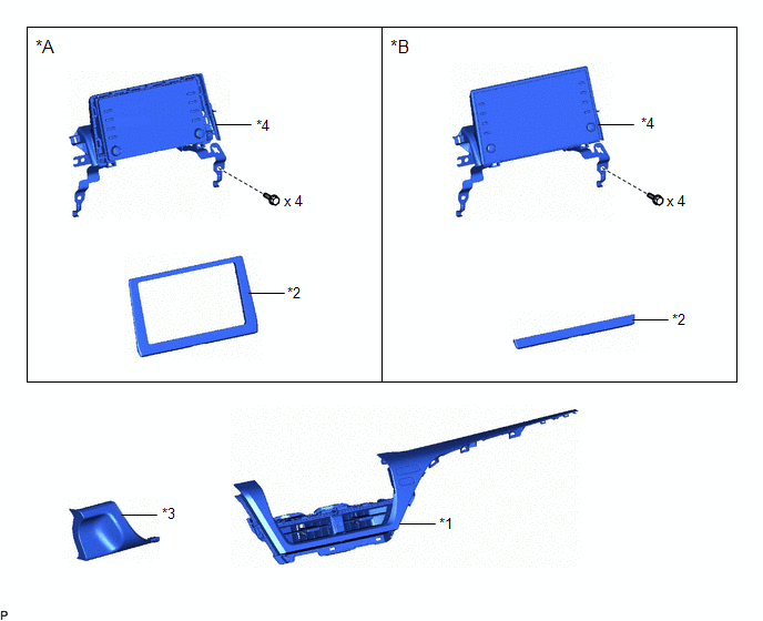
ILLUSTRATION
|
*A | for 7 Inch Display |
*B | for 9 Inch Display |
|
*1 | CENTER INSTRUMENT CLUSTER FINISH PANEL ASSEMBLY |
*2 | CENTER INSTRUMENT CLUSTER FINISH PANEL SUB-ASSEMBLY |
|
*3 | LOWER INSTRUMENT PANEL FINISH PANEL ASSEMBLY |
*4 | RADIO AND DISPLAY RECEIVER ASSEMBLY WITH BRACKET |
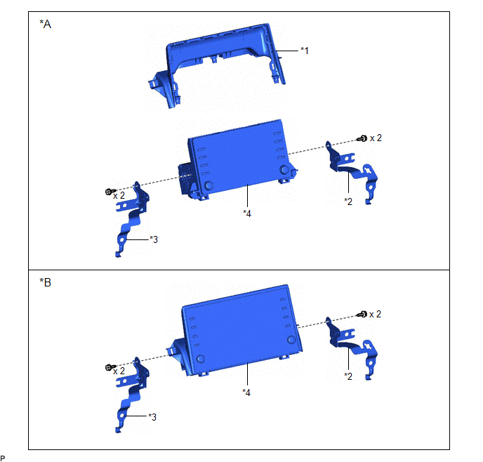
ILLUSTRATION
|
*A | for 7 Inch Display |
*B | for 9 Inch Display |
|
*1 | CENTER INSTRUMENT CLUSTER FINISH UPPER PANEL ASSEMBLY |
*2 | NO. 1 RADIO RECEIVER BRACKET |
|
*3 | NO. 2 RADIO RECEIVER BRACKET |
*4 | RADIO AND DISPLAY RECEIVER ASSEMBLY |
READ NEXT:
 Removal
REMOVAL PROCEDURE 1. PRECAUTION (w/o Navigation System)
NOTICE:
When replacing the radio and display receiver assembly, always replace it with a new one. If a radio and display receiver assembly
Installation
INSTALLATION PROCEDURE 1. PRECAUTION (w/o Navigation System)
NOTICE:
When replacing the radio and display receiver assembly, always replace it with a new one. If a radio and display receiver ass
SEE MORE:
Inspection
INSPECTION PROCEDURE 1. INSPECT FLOW SHUTTING VALVE (WATER BY-PASS HOSE ASSEMBLY)
(a) Measure the resistance according to the value(s) in the table below.
Standard Resistance:
Tester Connection Condition
Specified Condition
1 - 2 20°C (68°F)
22 to 28 ]
Intake Air Temperature Sensor 1 Bank 1 Circuit Short to Ground (P011011)
DESCRIPTION
The intake air temperature sensor, mounted on the mass air flow meter sub-assembly, monitors the intake air temperature. The intake air temperature sensor has a built-in thermistor with a resistance that varies according to the temperature of the intake air. When the intake air temper
© 2023-2026 Copyright www.tocamry.com
