Toyota Camry (XV70): Components
COMPONENTS
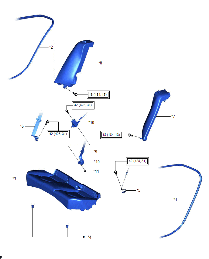
ILLUSTRATION
|
*1 | REAR DOOR OPENING TRIM WEATHERSTRIP LH |
*2 | REAR DOOR OPENING TRIM WEATHERSTRIP RH |
|
*3 | REAR SEAT CUSHION ASSEMBLY |
*4 | REAR SEAT CUSHION LOCK HOOK |
|
*5 | REAR SEAT OUTER BELT ASSEMBLY LH |
*6 | REAR SEAT OUTER BELT ASSEMBLY RH |
|
*7 | REAR SIDE SEATBACK ASSEMBLY LH |
*8 | REAR SIDE SEATBACK ASSEMBLY RH |
|
*9 | REAR CENTER SEAT OUTER BELT ASSEMBLY |
*10 | REAR SEAT INNER BELT ASSEMBLY RH |
|
*11 | WASHER |
- | - |
.png) |
Tightening torque for "Major areas involving basic vehicle performance such as moving/turning/stopping": N*m (kgf*cm, ft.*lbf) |
● | Non-reusable part |
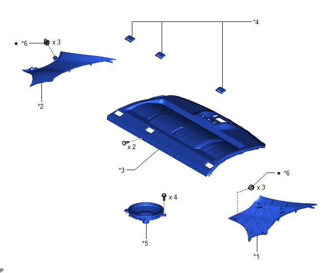
ILLUSTRATION
|
*1 | INNER ROOF SIDE GARNISH LH |
*2 | INNER ROOF SIDE GARNISH RH |
|
*3 | PACKAGE TRAY TRIM PANEL ASSEMBLY |
*4 | REAR SEAT SHOULDER BELT HOLE COVER |
|
*5 | REAR STEREO COMPONENT SPEAKER ASSEMBLY |
*6 | CLIP |
|
● | Non-reusable part |
- | - |
READ NEXT:
 Removal
REMOVAL CAUTION / NOTICE / HINT
The necessary procedures (adjustment, calibration, initialization, or registration) that must be performed after parts are removed and installed, or replaced during r
Inspection
INSPECTION PROCEDURE 1. INSPECT REAR STEREO COMPONENT SPEAKER ASSEMBLY
(a) With the speaker installed, check that there is no looseness or other abnormalities.
(b) Check that there is no foreign m
Installation
INSTALLATION PROCEDURE 1. INSTALL REAR STEREO COMPONENT SPEAKER ASSEMBLY
NOTICE: Do not touch the speaker cone. (a) Connect the connector.
(b) Engage the guide to temporarily install the rear ster
SEE MORE:
Initialization not Completed (C2177)
DESCRIPTION Initialization is necessary if one of the following occurs:
The tire pressure warning ECU and receiver is replaced.
A tire pressure warning valve and transmitter is replaced.
Tires with different standard tire pressures are installed.
The tires are rotated.
A new veh
Engine Coolant Temperature Sensor 1 Circuit Short to Battery or Open (P011515)
DESCRIPTION Refer to DTC P011511. Click here
HINT: When DTC P011515 is stored, the ECM enters fail-safe mode. During fail-safe mode, the engine coolant temperature is estimated to be 80°C (176°F) by the ECM. Fail-safe mode continues until a pass condition is detected.
DTC No. Detection
© 2023-2026 Copyright www.tocamry.com
