Toyota Camry (XV70): Components
Toyota Camry Repair Manual XV70 (2018-2024) / Brake / Brake System (other) / Brake Pedal / Components
COMPONENTS
ILLUSTRATION
|
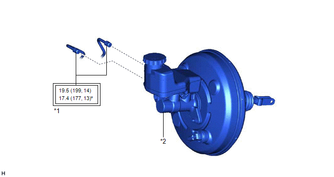
*1 | BRAKE LINE |
*2 | BRAKE MASTER CYLINDER SUB-ASSEMBLY |
.png) |
Tightening torque for "Major areas involving basic vehicle performance such as moving/turning/stopping" : N*m (kgf*cm, ft.*lbf) |
* | For use with a union nut wrench |
ILLUSTRATION
.png)
|
*1 | NO. 1 INSTRUMENT PANEL UNDER COVER SUB-ASSEMBLY |
- | - |
ILLUSTRATION
|
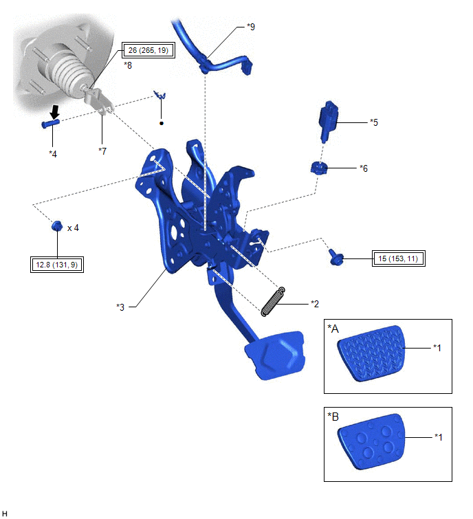
*A | w/ Rubber Pad |
*B | w/ Aluminum Pad |
|
*1 | BRAKE PEDAL PAD |
*2 | BRAKE PEDAL RETURN SPRING |
|
*3 | BRAKE PEDAL SUPPORT ASSEMBLY |
*4 | PUSH ROD PIN |
|
*5 | STOP LIGHT SWITCH ASSEMBLY |
*6 | STOP LIGHT SWITCH MOUNTING ADJUSTER |
|
*7 | BRAKE MASTER CYLINDER PUSH ROD CLEVIS |
*8 | LOCK NUT |
|
*9 | WIRE HARNESS |
- | - |
|
|
Tightening torque for "Major areas involving basic vehicle performance such as moving/turning/stopping" : N*m (kgf*cm, ft.*lbf) |
● | Non-reusable part |
.png) |
Lithium soap base glycol grease |
- | - |
READ NEXT:
 Removal
REMOVAL CAUTION / NOTICE / HINT
The necessary procedures (adjustment, calibration, initialization or registration) that must be performed after parts are removed and installed, or replaced during br
Adjustment
ADJUSTMENT PROCEDURE 1. INSPECT AND ADJUST BRAKE PEDAL HEIGHT
(a) Remove the front door scuff plate LH. Click here
(b) Remove the cowl side trim sub-assembly LH.
Click here (c) Remove the No
Installation
INSTALLATION PROCEDURE 1. INSTALL BRAKE PEDAL PAD
(a) Install the brake pedal pad to the brake pedal support assembly. 2. INSTALL STOP LIGHT SWITCH MOUNTING ADJUSTER
(a) Engage the 2 claws to inst
SEE MORE:
Disassembly
DISASSEMBLY PROCEDURE 1. REMOVE REAR CENTER ULTRASONIC SENSOR (w/ Parking Support Brake System)
Click here HINT: Use the same procedure for the RH side and LH side.
2. REMOVE REAR CORNER ULTRASONIC SENSOR (w/ Parking Support Brake System)
Click here HINT: Use the same procedure for the
Components
COMPONENTS ILLUSTRATION
*A for Type A
*B w/o Panoramic View Monitor System
*C w/ Panoramic View Monitor System
- -
*1 OUTER MIRROR
*2 OUTER MIRROR COVER
*3 OUTER MIRROR COVER WITH OUTER MIRROR HOLE COVER
*4 OUTER MIR
© 2023-2026 Copyright www.tocamry.com
