Toyota Camry (XV70): Components
COMPONENTS
ILLUSTRATION
.png)
|
*1 | BATTERY CLAMP SUB-ASSEMBLY |
- | - |
.png) |
N*m (kgf*cm, ft.*lbf): Specified torque |
- | - |
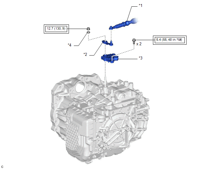
ILLUSTRATION
|
*1 | TRANSMISSION CONTROL CABLE ASSEMBLY |
*2 | TRANSMISSION CONTROL SHAFT LEVER |
|
*3 | PARK/NEUTRAL POSITION SWITCH ASSEMBLY |
*4 | WASHER |
.png) |
Tightening torque for "Major areas involving basic vehicle performance such as moving/turning/stopping": N*m (kgf*cm, ft.*lbf) |
- | - |
READ NEXT:
 On-vehicle Inspection
ON-VEHICLE INSPECTION PROCEDURE
1. SECURE VEHICLE (a) Fully apply the parking brake and chock a wheel.
CAUTION:
Make sure to apply the parking brake and chock a wheel before performing this pr
Removal
REMOVAL CAUTION / NOTICE / HINT
The necessary procedures (adjustment, calibration, initialization or registration) that must be performed after parts are removed and installed, or replaced during pa
Inspection
INSPECTION PROCEDURE 1. INSPECT PARK/NEUTRAL POSITION SWITCH ASSEMBLY
NOTICE: Both the park/neutral position switch assembly and transmission control shaft lever are available in two different shape
SEE MORE:
Brake Warning Light (Yellow) Remains On
DESCRIPTION This procedure is for troubleshooting when the brake warning light (yellow) remains on but no DTCs are output.
The skid control ECU (brake actuator assembly) controls the brake warning light (yellow) in the combination meter assembly via CAN communication. PROCEDURE
1.
CHECK
Vehicle Speed Sensor "A" No Signal (P050031)
DESCRIPTION The speed sensor detects the wheel speed and sends the appropriate signals to the skid control ECU. The skid control ECU converts these wheel speed signals into a pulse signal and outputs it to the ECM via the combination meter. The ECM determines the vehicle speed based on the frequency
© 2023-2026 Copyright www.tocamry.com
