Toyota Camry (XV70): Components
COMPONENTS
ILLUSTRATION
|
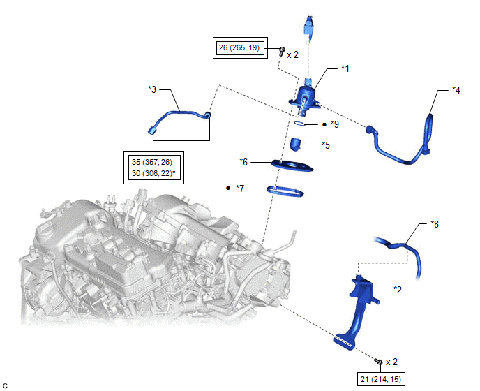
*1 | FUEL PUMP ASSEMBLY |
*2 | FUEL PUMP PROTECTOR |
|
*3 | NO. 1 FUEL PIPE SUB-ASSEMBLY |
*4 | NO. 2 FUEL TUBE SUB-ASSEMBLY |
|
*5 | FUEL PUMP LIFTER ASSEMBLY |
*6 | FUEL PUMP LIFTER GUIDE |
|
*7 | FUEL PUMP SPACER GASKET |
*8 | FUEL TUBE SUB-ASSEMBLY |
|
*9 | O-RING |
- | - |
.png) |
Tightening torque for "Major areas involving basic vehicle performance such as moving/turning/stopping": N*m (kgf*cm, ft.*lbf) |
.png) |
N*m (kgf*cm, ft.*lbf): Specified torque |
|
* | For use with a union nut wrench |
● | Non-reusable part |
READ NEXT:
 On-vehicle Inspection
ON-VEHICLE INSPECTION PROCEDURE
1. FUEL PUMP ASSEMBLY OPERATION (a) Check fuel pressure. (1) Connect the Techstream to the DLC3.
(2) Start the engine. (3) Turn the Techstream on. (4) Enter the fol
Removal
REMOVAL CAUTION / NOTICE / HINT
The necessary procedures (adjustment, calibration, initialization or registration) that must be performed after parts are removed and installed, or replaced during fu
Inspection
INSPECTION PROCEDURE 1. INSPECT FUEL PUMP ASSEMBLY
(a) Measure the resistance according to the value(s) in the table below.
Standard Resistance:
Tester Connection Condition
Sp
SEE MORE:
Using an anchor bracket (for top tether strap)
■ Anchor brackets (for top tether strap)
Anchor brackets are provided for each rear seat.
Use anchor brackets when fixing the top tether strap.
Seats with an adjustable type head restraint
Seats with an integrated type
head restraint
■ Fixing the top tether strap to the anchor bracke
Installation
INSTALLATION PROCEDURE 1. INSTALL STUD BOLT
HINT: If a stud bolt is deformed or the threads are damaged, replace it.
(a) Using an E6 "TORX" socket wrench, install the 2 stud bolts to the intake manifold.
Torque: 10 N·m {102 kgf·cm, 7 ft·lbf}
2. INSTALL NO. 1 INTAKE M
© 2023-2026 Copyright www.tocamry.com
