Toyota Camry (XV70): Removal
REMOVAL
CAUTION / NOTICE / HINT
The necessary procedures (adjustment, calibration, initialization or registration) that must be performed after parts are removed and installed, or replaced during fuel pump assembly removal/installation are shown below.
Necessary Procedures After Parts Removed/Installed/Replaced|
Replaced Part or Performed Procedure |
Necessary Procedure | Effect/Inoperative Function when Necessary Procedure not Performed |
Link |
|---|---|---|---|
|
Battery terminal is disconnected/reconnected |
Perform steering sensor zero point calibration |
Lane Tracing Assist System |
|
|
Pre-collision System | |||
|
Memorize steering angle neutral point |
Parking Assist Monitor System |
| |
|
Panoramic View Monitor System |
| ||
| Inspection after repair |
|
|
CAUTION:
- Never perform work on fuel system components near any possible ignition sources.
.png)
- Vaporized fuel could ignite, resulting in a serious accident.
- Do not perform work on fuel system components without first disconnecting the cable from the negative (-) battery terminal.
.png)
- Sparks could cause vaporized fuel to ignite, resulting in a serious accident.
- To prevent serious injury due to fuel spray from the high-pressure fuel lines, always discharge fuel system pressure before removing any fuel system components.
.png)
PROCEDURE
1. PRECAUTION
NOTICE:
After turning the engine switch off, waiting time may be required before disconnecting the cable from the negative (-) battery terminal. Therefore, make sure to read the disconnecting the cable from the negative (-) battery terminal notices before proceeding with work.
Click here .gif)
2. DISCHARGE FUEL SYSTEM PRESSURE
Click here
3. DISCONNECT CABLE FROM NEGATIVE BATTERY TERMINAL
NOTICE:
When disconnecting the cable, some systems need to be initialized after the cable is reconnected.
Click here
4. REMOVE INTAKE MANIFOLD
Click here
5. REMOVE FUEL PUMP PROTECTOR
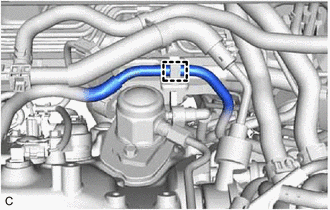
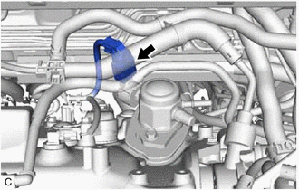
| (a) Disengage the clamp to disconnect the fuel tube sub-assembly from the fuel pump protector. |
|
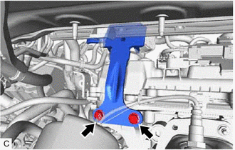
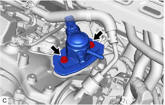
| (b) Remove the 2 bolts and fuel pump protector from the cylinder head sub-assembly. |
|
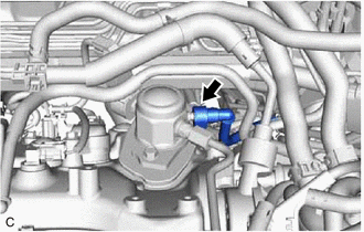
6. DISCONNECT NO. 2 FUEL TUBE SUB-ASSEMBLY
| (a) Disconnect the No. 2 fuel tube sub-assembly from the fuel pump assembly. Click here |
|
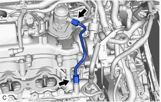
7. REMOVE NO. 1 FUEL PIPE SUB-ASSEMBLY
CAUTION:
To prevent serious injury due to fuel spray from the high-pressure fuel lines, always discharge fuel system pressure before removing any fuel system components.
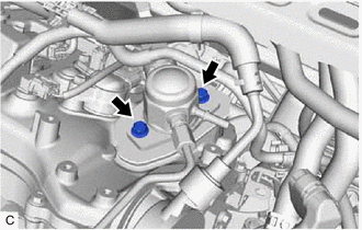
| (a) Using a 17 mm union nut wrench, loosen the 2 union nuts of the No. 1 fuel pipe sub-assembly. |
|
| (b) Loosen the 2 bolts of the fuel pump assembly. |
|
(c) Remove the No. 1 fuel pipe sub-assembly from the fuel delivery pipe RH and fuel pump assembly.
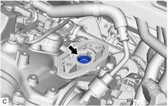
8. REMOVE FUEL (ENGINE ROOM SIDE) PUMP ASSEMBLY
| (a) Disconnect the fuel pump assembly connector. |
|
| (b) Remove the 2 bolts, fuel pump assembly and fuel pump lifter guide from the cylinder head cover sub-assembly. |
|
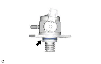
| (c) Remove the O-ring from the fuel pump assembly. |
|
| (d) Remove the fuel pump lifter assembly from the fuel pump lifter housing. |
|
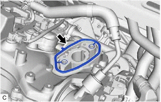
| (e) Remove the fuel pump spacer gasket from the cylinder head cover sub-assembly. |
|
READ NEXT:
 Inspection
INSPECTION PROCEDURE 1. INSPECT FUEL PUMP ASSEMBLY
(a) Measure the resistance according to the value(s) in the table below.
Standard Resistance:
Tester Connection Condition
Sp
Installation
INSTALLATION PROCEDURE 1. TEMPORARILY INSTALL FUEL (ENGINE ROOM SIDE) PUMP ASSEMBLY
(a) Turn the crankshaft pulley until the flat of the camshaft faces the fuel pump lifter assembly.
HINT: Th
Components
COMPONENTS ILLUSTRATION
*1 FUEL PUMP ASSEMBLY
*2 FUEL PUMP PROTECTOR
*3 NO. 1 FUEL PIPE SUB-ASSEMBLY
*4 NO. 2 FUEL TUBE SUB-ASSEMBLY
*5 FUEL PUMP LIFTER
SEE MORE:
Removal
REMOVAL CAUTION / NOTICE / HINT
The necessary procedures (adjustment, calibration, initialization or registration) that must be performed after parts are removed and installed, or replaced during tire pressure warning valve and transmitter removal/installation are shown below. Necessary Procedures
Components
COMPONENTS ILLUSTRATION
*A w/o Courtesy Light
*B w/ Courtesy Light
*C for Front Passenger Side
*D for Driver Side
*1 COURTESY LIGHT ASSEMBLY
*2 FRONT ARMREST ASSEMBLY
*3 FRONT DOOR ARMREST COVER SUB-ASSEMBLY
*4 FRONT
