Toyota Camry (XV70): Installation
INSTALLATION
PROCEDURE
1. TEMPORARILY INSTALL FUEL (ENGINE ROOM SIDE) PUMP ASSEMBLY
| (a) Turn the crankshaft pulley until the flat of the camshaft faces the fuel pump lifter assembly. HINT: This prevents the camshaft nose from pushing up the fuel pump lifter assembly when installing the fuel pump assembly. |
|
(b) Fill the fuel pump lifter housing oil collection areas with 30 cc (1.8 cu. in.) of engine oil from the fuel pump assembly hole of the cylinder head cover sub-assembly.
| (c) Apply engine oil to the pump drive cam and fuel pump lifter assembly. |
|
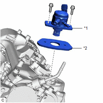
(d) Install a new fuel pump spacer gasket to the cylinder head cover sub-assembly.
| (e) Apply engine oil to the inside of the fuel pump lifter housing and the outside of the fuel pump lifter assembly. |
|
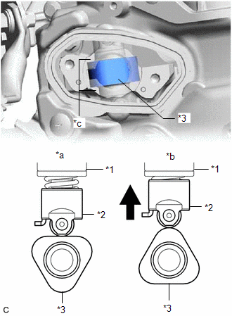
(f) Set the fuel pump lifter assembly on the fuel pump lifter housing as shown in the illustration.
HINT:
Align the stopper key of the fuel pump lifter assembly with the key groove of the fuel pump lifter housing.
(g) Apply engine oil to a new O-ring and install it to the fuel pump assembly.
NOTICE:
Do not damage the O-ring.
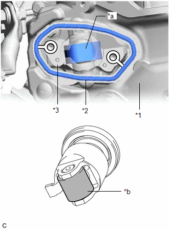
| (h) Set the fuel pump lifter guide and fuel pump assembly on the cylinder head cover sub-assembly as shown in the illustration. |
|
(i) Temporarily install the fuel pump assembly with the 2 bolts, leaving some allowance for left and right movement.
2. TEMPORARILY INSTALL NO. 1 FUEL PIPE SUB-ASSEMBLY
NOTICE:
Do not damage the seals of the union nuts of the No. 1 fuel pipe sub-assembly.
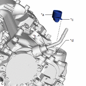
(a) Temporarily install the No. 1 fuel pipe sub-assembly to the fuel delivery pipe RH and tighten the union nut by hand.
(b) Temporarily install the No. 1 fuel pipe sub-assembly to the fuel pump assembly and tighten the union nut by hand.
3. INSTALL FUEL (ENGINE ROOM SIDE) PUMP ASSEMBLY
HINT:
Perform "Inspection After Repair" after replacing the fuel pump assembly.
Click here .gif)
(a) Tighten the 2 bolts.
Torque:
26 N·m {265 kgf·cm, 19 ft·lbf}
(b) Connect the fuel pump assembly connector.
4. INSTALL NO. 1 FUEL PIPE SUB-ASSEMBLY
| (a) Using a 17 mm union nut wrench, tighten the union nut on the fuel pump assembly side of the No. 1 fuel pipe sub-assembly. Torque: Specified tightening torque : 35 N·m {357 kgf·cm, 26 ft·lbf} NOTICE: Do not adjust the torque in the loosening direction. HINT:
|
|
(b) Using a 17 mm union nut wrench, tighten the union nut on the fuel delivery pipe RH side of the No. 1 fuel pipe sub-assembly.
Torque:
Specified tightening torque :
35 N·m {357 kgf·cm, 26 ft·lbf}
NOTICE:
Do not adjust the torque in the loosening direction.
HINT:
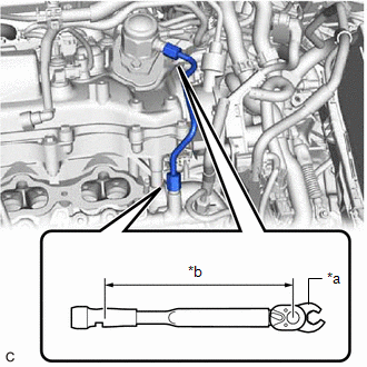
- Calculate the torque wrench reading when changing the fulcrum length of the torque wrench.
Click here
- When using a 17 mm union nut wrench (fulcrum length of 30 mm (1.18 in.)) + torque wrench (fulcrum length of 180 mm (7.09 in.)): 30 N*m (306 kgf*cm, 22 ft.*lbf)
5. CONNECT NO. 2 FUEL TUBE SUB-ASSEMBLY
(a) Connect the No. 2 fuel tube sub-assembly to the fuel pump assembly.
Click here
6. INSTALL FUEL PUMP PROTECTOR
(a) Install the fuel pump protector to the cylinder head sub-assembly with the 2 bolts.
Torque:
21 N·m {214 kgf·cm, 15 ft·lbf}
(b) Engage the clamp to connect the fuel tube sub-assembly to the fuel pump protector.
7. INSTALL INTAKE MANIFOLD
Click here
8. CONNECT CABLE TO NEGATIVE BATTERY TERMINAL
NOTICE:
When disconnecting the cable, some systems need to be initialized after the cable is reconnected.
Click here
9. INSPECT FOR FUEL LEAK
Click here
10. PERFORM INITIALIZATION
(a) Perform "Inspection After Repair" after replacing the fuel pump assembly.
Click here
READ NEXT:
 Components
COMPONENTS ILLUSTRATION
*1 FUEL PUMP ASSEMBLY
*2 FUEL PUMP PROTECTOR
*3 NO. 1 FUEL PIPE SUB-ASSEMBLY
*4 NO. 2 FUEL TUBE SUB-ASSEMBLY
*5 FUEL PUMP LIFTER
On-vehicle Inspection
ON-VEHICLE INSPECTION PROCEDURE
1. FUEL PUMP ASSEMBLY OPERATION (a) Check fuel pressure. (1) Connect the Techstream to the DLC3.
(2) Start the engine. (3) Turn the Techstream on. (4) Enter the fol
Removal
REMOVAL CAUTION / NOTICE / HINT
The necessary procedures (adjustment, calibration, initialization or registration) that must be performed after parts are removed and installed, or replaced during fu
SEE MORE:
Software Incompatibility with Brake System Control Module Invalid/Incompatible Software Component (U031857)
DESCRIPTION If the vehicle information stored in the forward recognition camera does not match the vehicle information sent from the skid control ECU (brake actuator assembly), the forward recognition camera stores DTC U031857.
DTC No. Detection Item
DTC Detection Condition Trouble Ar
Reassembly
REASSEMBLY PROCEDURE 1. INSTALL FRONT BUMPER SIDE RETAINER LH
(a) Engage the 2 clips as shown in the illustration.
Install in this Direction
(b) Install the front bumper side retainer LH with the bolt.
Torque: 7.0 N
