Toyota Camry (XV70): Inspection
INSPECTION
PROCEDURE
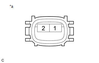
1. INSPECT FUEL PUMP ASSEMBLY
| (a) Measure the resistance according to the value(s) in the table below. Standard Resistance:
If the result is not as specified, replace the fuel pump assembly. |
|
READ NEXT:
 Installation
INSTALLATION PROCEDURE 1. TEMPORARILY INSTALL FUEL (ENGINE ROOM SIDE) PUMP ASSEMBLY
(a) Turn the crankshaft pulley until the flat of the camshaft faces the fuel pump lifter assembly.
HINT: Th
Components
COMPONENTS ILLUSTRATION
*1 FUEL PUMP ASSEMBLY
*2 FUEL PUMP PROTECTOR
*3 NO. 1 FUEL PIPE SUB-ASSEMBLY
*4 NO. 2 FUEL TUBE SUB-ASSEMBLY
*5 FUEL PUMP LIFTER
On-vehicle Inspection
ON-VEHICLE INSPECTION PROCEDURE
1. FUEL PUMP ASSEMBLY OPERATION (a) Check fuel pressure. (1) Connect the Techstream to the DLC3.
(2) Start the engine. (3) Turn the Techstream on. (4) Enter the fol
SEE MORE:
Reassembly
REASSEMBLY CAUTION / NOTICE / HINT
HINT:
Use the same procedure for the RH side and LH side.
The following procedure is for the LH side.
PROCEDURE 1. INSTALL HEADLIGHT COVER (for LED Type Turn Signal Light)
(a) Install the 2 headlight covers.
2. INSTALL
Removal
REMOVAL CAUTION / NOTICE / HINT
The necessary procedures (adjustment, calibration, initialization, or registration) that must be performed after parts are removed and installed, or replaced during rear coil spring removal/installation are shown below. Necessary Procedures After Parts Removed/Insta
© 2023-2026 Copyright www.tocamry.com
