Toyota Camry (XV70): Components
COMPONENTS
ILLUSTRATION
.png)
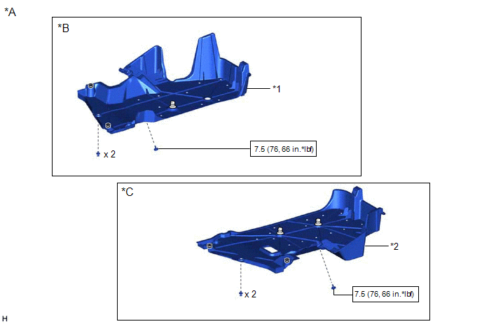
|
*A | for 2WD |
*B | for RH Side |
|
*C | for LH Side |
- | - |
|
*1 | NO. 1 FLOOR UNDER COVER |
*2 | NO. 2 FLOOR UNDER COVER |
.png) |
N*m (kgf*cm, ft.*lbf): Specified torque |
- | - |
ILLUSTRATION
|
*A | for AWD |
*B | for RH Side |
|
*C | for LH Side |
- | - |
|
*1 | NO. 1 FLOOR UNDER COVER |
*2 | NO. 2 FLOOR UNDER COVER |
|
|
N*m (kgf*cm, ft.*lbf): Specified torque |
- | - |
ILLUSTRATION
|
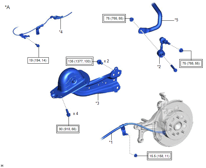
*A | for 2WD without Electric Parking Brake System |
- | - |
|
*1 | NO. 3 PARKING BRAKE CABLE ASSEMBLY |
*2 | REAR STABILIZER LINK ASSEMBLY |
|
*3 | REAR TRAILING ARM ASSEMBLY |
*4 | SKID CONTROL SENSOR WIRE |
|
*5 | REAR STABILIZER BAR |
- | - |
.png) |
Tightening torque for "Major areas involving basic vehicle performance such as moving/turning/stopping": N*m (kgf*cm, ft.*lbf) |
|
N*m (kgf*cm, ft.*lbf): Specified torque |
ILLUSTRATION
|
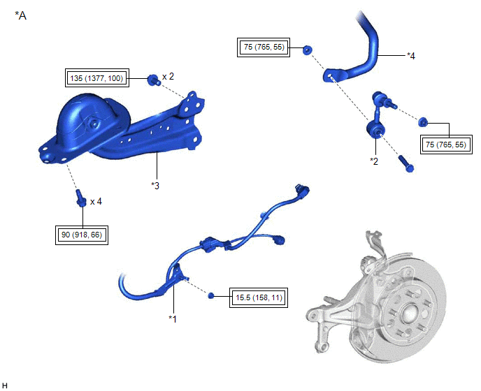
*A | for 2WD with Electric Parking Brake System |
- | - |
|
*1 | NO. 2 PARKING BRAKE WIRE ASSEMBLY |
*2 | REAR STABILIZER LINK ASSEMBLY |
|
*3 | REAR TRAILING ARM ASSEMBLY |
*4 | REAR STABILIZER BAR |
|
|
Tightening torque for "Major areas involving basic vehicle performance such as moving/turning/stopping": N*m (kgf*cm, ft.*lbf) |
- | - |
ILLUSTRATION
|
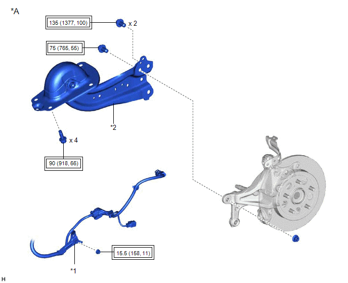
*A | for AWD |
- | - |
|
*1 | NO. 2 PARKING BRAKE WIRE ASSEMBLY |
*2 | REAR TRAILING ARM ASSEMBLY |
|
|
Tightening torque for "Major areas involving basic vehicle performance such as moving/turning/stopping": N*m (kgf*cm, ft.*lbf) |
- | - |
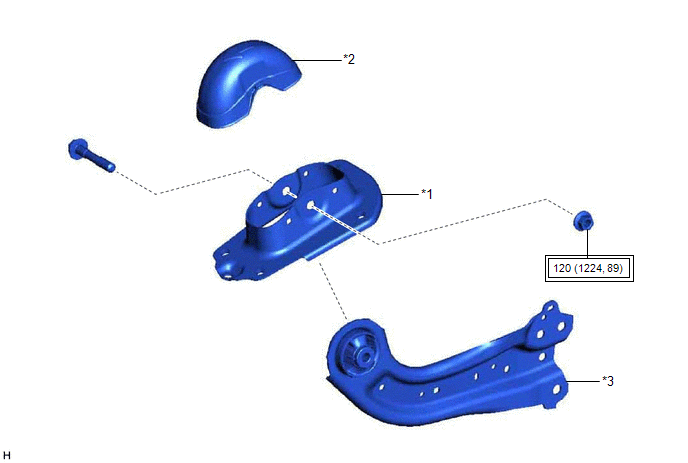
ILLUSTRATION
|
*1 | REAR SUSPENSION ARM BRACKET |
*2 | REAR SUSPENSION ARM COVER |
|
*3 | REAR TRAILING ARM ASSEMBLY |
- | - |
|
|
Tightening torque for "Major areas involving basic vehicle performance such as moving/turning/stopping": N*m (kgf*cm, ft.*lbf) |
- | - |
READ NEXT:
 Removal
REMOVAL CAUTION / NOTICE / HINT
The necessary procedures (adjustment, calibration, initialization, or registration) that must be performed after parts are removed and installed, or replaced during r
Installation
INSTALLATION CAUTION / NOTICE / HINT
HINT:
Use the same procedure for the RH side and LH side.
The following procedure is for the LH side.
PROCEDURE 1. INSTALL REAR SUSPENSION ARM BRACKE
SEE MORE:
Transmission Control Switch Circuit
DESCRIPTION When the shift lever is in S and moved toward "-" or "+", it is possible to select different shift ranges (S1 to S8).
Moving the shift lever toward "+" increases the shift range by one, and moving the shift lever toward "-" decreases the shift range by one. WIRING DIAGRAM
CAUTION /
Components
COMPONENTS ILLUSTRATION
*1 COWL SIDE TRIM SUB-ASSEMBLY LH
*2 FRONT DOOR OPENING TRIM WEATHERSTRIP LH
*3 FRONT DOOR SCUFF PLATE LH
*4 HOOD LOCK CONTROL LEVER SUB-ASSEMBLY
*5 INSTRUMENT SIDE PANEL LH
*6 LUGGAGE COMPARTMENT DOOR OPENING SW
