Toyota Camry (XV70): Components
COMPONENTS
ILLUSTRATION
|
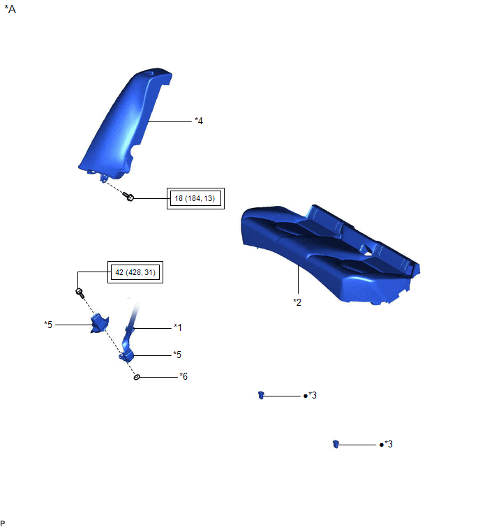
*A | for Fold Down Seat Type |
- | - |
|
*1 | REAR CENTER SEAT OUTER BELT ASSEMBLY |
*2 | REAR SEAT CUSHION ASSEMBLY |
|
*3 | REAR SEAT CUSHION LOCK HOOK |
*4 | REAR SIDE SEATBACK ASSEMBLY RH |
|
*5 | REAR SEAT INNER BELT ASSEMBLY RH |
*6 | WASHER |
.png) |
Tightening torque for "Major areas involving basic vehicle performance such as moving/turning/stopping": N*m (kgf*cm, ft.*lbf) |
● | Non-reusable part |
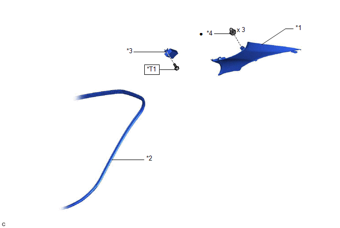
ILLUSTRATION
|
*1 | INNER ROOF SIDE GARNISH RH |
*2 | REAR DOOR OPENING TRIM WEATHERSTRIP RH |
|
*3 | TIRE PRESSURE WARNING ECU AND RECEIVER |
*4 | CLIP |
.png) |
N*m (kgf*cm, ft.*lbf): Specified torque |
● | Non-reusable part |
|
*T1 | for Type A: 8.3 (85, 73 in.*lbf) for Type B: 10 (102, 7) |
- | - |
READ NEXT:
 Removal
REMOVAL CAUTION / NOTICE / HINT
The necessary procedures (adjustment, calibration, initialization or registration) that must be performed after parts are removed and installed, or replaced during do
Installation
INSTALLATION PROCEDURE 1. INSTALL TIRE PRESSURE WARNING ECU AND RECEIVER
NOTICE:
Do not drop, strike or otherwise subject the tire pressure warning ECU and receiver to impact.
If the tire p
SEE MORE:
Left Front Wheel Speed Sensor Circuit Short to Battery (C050012)
DESCRIPTION Each speed sensor detects wheel speed and sends signals to the skid control ECU (brake actuator assembly). These signals are used by the ABS control.
The speed sensor detects the magnetic fields of the speed sensor rotor as it rotates and outputs a pulse signal.
The frequency of the
Rear Door Opening Trim Weatherstrip
ComponentsCOMPONENTS ILLUSTRATION
*1 REAR DOOR OPENING TRIM WEATHERSTRIP
*2 REAR DOOR SCUFF PLATE RemovalREMOVAL CAUTION / NOTICE / HINT
HINT:
Use the same procedure for the RH side and LH side.
The following procedure is for the LH side.
PROCEDURE 1. RE
© 2023-2026 Copyright www.tocamry.com
