
Toyota Camry (XV70): Components
COMPONENTS
ILLUSTRATION
.png)
|
*1 | REAR ARMREST ASSEMBLY |
*2 | REAR DOOR ARMREST COVER SUB-ASSEMBLY |
|
*3 | REAR DOOR INNER GLASS WEATHERSTRIP |
*4 | REAR DOOR NO. 2 SERVICE HOLE COVER |
|
*5 | REAR DOOR TRIM BOARD SUB-ASSEMBLY |
*6 | REAR POWER WINDOW REGULATOR SWITCH ASSEMBLY WITH REAR DOOR UPPER ARMREST BASE PANEL |
|
*7 | NO. 1 DOOR SCUFF PLATE CLAMP |
- | - |
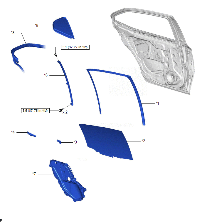
ILLUSTRATION
|
*1 | REAR DOOR GLASS RUN |
*2 | REAR DOOR GLASS SUB-ASSEMBLY |
|
*3 | REAR DOOR NO. 1 VENT SEAL |
*4 | REAR DOOR PANEL PROTECTOR |
|
*5 | REAR DOOR QUARTER WINDOW GLASS |
*6 | REAR DOOR REAR LOWER WINDOW FRAME SUB-ASSEMBLY |
|
*7 | REAR DOOR SERVICE HOLE COVER |
*8 | REAR DOOR WEATHERSTRIP |
.png) |
N*m (kgf*cm, ft.*lbf): Specified torque |
- | - |
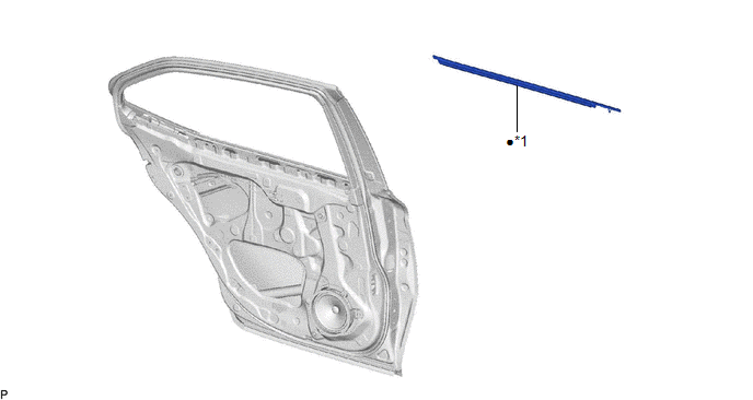
ILLUSTRATION
|
*1 | REAR DOOR BELT MOULDING ASSEMBLY |
- | - |
|
● | Non-reusable part |
- | - |
READ NEXT:
 Removal
REMOVAL CAUTION / NOTICE / HINT
The necessary procedures (adjustment, calibration, initialization or registration) that must be performed after parts are removed and installed, or replaced during r
Installation
INSTALLATION CAUTION / NOTICE / HINT
HINT:
Use the same procedure for the RH side and LH side.
The following procedure is for the LH side.
PROCEDURE 1. INSTALL REAR DOOR BELT MOULDI
SEE MORE:
Problem Symptoms Table
PROBLEM SYMPTOMS TABLE If DTCs are not output but the malfunction persists, use the following table to determine which circuits to inspect for each problem symptom.
HINT: Refer to each inspection procedure for related problem symptoms. Vehicle Stability Control System
Symptom Suspected Are
Remote Control System does not Operate
DESCRIPTION The main body ECU (multiplex network body ECU) receives remote control signals from the driver door key cylinder or wireless transmitter. Then, the main body ECU (multiplex network body ECU) activates the power window motor and sends the remote control signals to the sliding roof ECU (sl
© 2023-2026 Copyright www.tocamry.com
