
Toyota Camry (XV70): Components
COMPONENTS
ILLUSTRATION
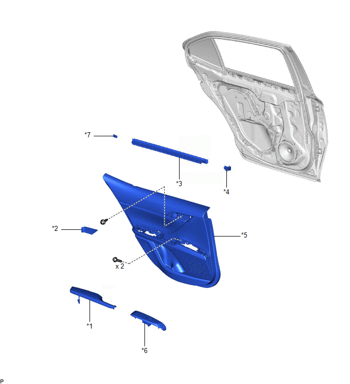
|
*1 | REAR ARMREST ASSEMBLY |
*2 | REAR DOOR ARMREST COVER SUB-ASSEMBLY |
|
*3 | REAR DOOR INNER GLASS WEATHERSTRIP |
*4 | REAR DOOR NO. 2 SERVICE HOLE COVER |
|
*5 | REAR DOOR TRIM BOARD SUB-ASSEMBLY |
*6 | REAR POWER WINDOW REGULATOR SWITCH ASSEMBLY WITH REAR DOOR UPPER ARMREST BASE PANEL |
|
*7 | NO. 1 DOOR SCUFF PLATE CLAMP |
- | - |
ILLUSTRATION
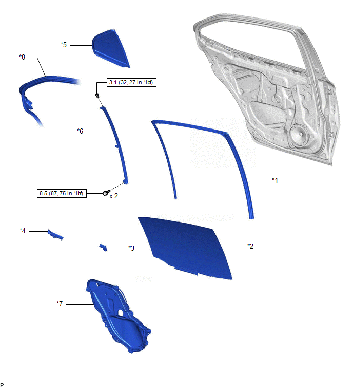
|
*1 | REAR DOOR GLASS RUN |
*2 | REAR DOOR GLASS SUB-ASSEMBLY |
|
*3 | REAR DOOR NO. 1 VENT SEAL |
*4 | REAR DOOR PANEL PROTECTOR |
|
*5 | REAR DOOR QUARTER WINDOW GLASS |
*6 | REAR DOOR REAR LOWER WINDOW FRAME SUB-ASSEMBLY |
|
*7 | REAR DOOR SERVICE HOLE COVER |
*8 | REAR DOOR WEATHERSTRIP |
.png) |
N*m (kgf*cm, ft.*lbf): Specified torque |
- | - |
ILLUSTRATION
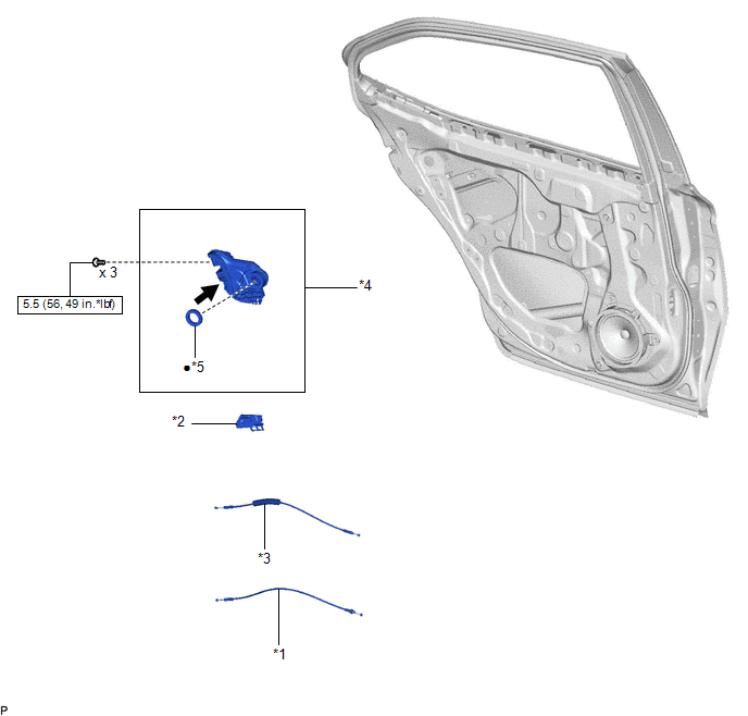
|
*1 | REAR DOOR INSIDE LOCKING CABLE ASSEMBLY |
*2 | REAR DOOR LOCK COVER SUB-ASSEMBLY |
|
*3 | REAR DOOR LOCK REMOTE CONTROL CABLE ASSEMBLY |
*4 | REAR DOOR LOCK WITH MOTOR ASSEMBLY |
|
*5 | DOOR LOCK WIRING HARNESS SEAL |
- | - |
|
|
N*m (kgf*cm, ft.*lbf): Specified torque |
? | Non-reusable part |
.png) |
MP grease | - |
- |
READ NEXT:
 Removal
REMOVAL CAUTION / NOTICE / HINT
The necessary procedures (adjustment, calibration, initialization, or registration) that must be performed after parts are removed and installed, or replaced during re
Inspection
INSPECTION PROCEDURE 1. INSPECT REAR DOOR LOCK WITH MOTOR ASSEMBLY LH
(a) Check the operation of the door lock motor. (1) Apply battery voltage and check the operation of the door lock motor.
O
Installation
INSTALLATION CAUTION / NOTICE / HINT
HINT:
Use the same procedure for the RH side and LH side.
The following procedure is for the LH side.
PROCEDURE 1. INSTALL REAR DOOR INSIDE LOCKING CABLE AS
SEE MORE:
Low Pressure Fuel System Pressure - Too Low (P008A00)
DESCRIPTION In order to supply the optimal fuel pressure according to the driving conditions and usage environment, the variable fuel system sends a drive signal from the ECM to the fuel pump control ECU assembly, steplessly performing variable control of the fuel pump (for low pressure side) and re
On-vehicle Inspection
ON-VEHICLE INSPECTION PROCEDURE
1. INSPECT STOP LIGHT SWITCH ASSEMBLY (a) Disconnect the A81 stop light switch assembly connector.
(b) Measure the voltage and resistance on the wire harness side connector according to the value(s) in the table below.
Standard Voltage:
Tester C
