Toyota Camry (XV70): Front Door Opening Trim Weatherstrip
Components
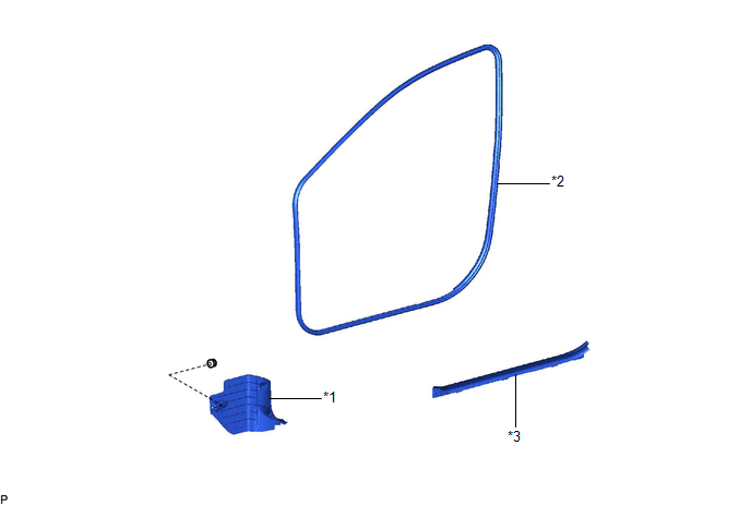
COMPONENTS
ILLUSTRATION
|
*1 | COWL SIDE TRIM SUB-ASSEMBLY |
*2 | FRONT DOOR OPENING TRIM WEATHERSTRIP |
|
*3 | FRONT DOOR SCUFF PLATE |
- | - |
Removal
REMOVAL
CAUTION / NOTICE / HINT
HINT:
- Use the same procedure for the RH side and LH side.
- The following procedure is for the LH side.
PROCEDURE
1. REMOVE FRONT DOOR SCUFF PLATE
Click here .gif)
2. REMOVE COWL SIDE TRIM SUB-ASSEMBLY
Click here
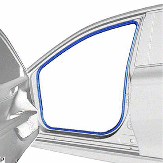
3. REMOVE FRONT DOOR OPENING TRIM WEATHERSTRIP
| (a) Remove the front door opening trim weatherstrip. |
|
Installation
INSTALLATION
CAUTION / NOTICE / HINT
HINT:
- Use the same procedure for the RH side and LH side.
- The following procedure is for the LH side.
PROCEDURE
1. INSTALL FRONT DOOR OPENING TRIM WEATHERSTRIP
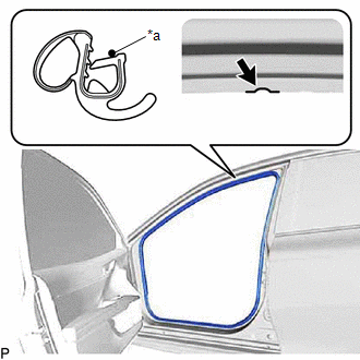
(a) Align the alignment mark on the front door opening trim weatherstrip with the flange on the vehicle body indicated by the arrow in the illustration, and install the front door opening trim weatherstrip.
|
*a | Alignment Mark |
.png) |
Flange Position |
NOTICE:
- Always align the alignment mark with the flange when installing the part. If the alignment mark is not aligned, water ingress may occur.
- After installation, check that the corners fit correctly.
HINT:
- Make sure to install the part of the front door opening trim weatherstrip near the alignment mark first.
- The color of the alignment marks on the front door opening trim weatherstrip LH and front door opening trim weatherstrip RH are different.
Alignment Mark:
Location
Color
for LH Side
Yellow
for RH Side
White
2. INSTALL COWL SIDE TRIM SUB-ASSEMBLY
Click here
.gif)
3. INSTALL FRONT DOOR SCUFF PLATE
Click here
READ NEXT:
 Components
COMPONENTS ILLUSTRATION
*1 LUGGAGE COMPARTMENT TRIM INNER COVER LH
*2 NO. 1 LUGGAGE COMPARTMENT TRIM HOOK
*3 REAR FLOOR FINISH PLATE
*4 SPARE WHEEL COVER AS
Removal
REMOVAL PROCEDURE 1. REMOVE SPARE WHEEL COVER ASSEMBLY
Click here 2. REMOVE SPARE WHEEL COVER TRAY
Click here 3. REMOVE NO. 1 LUGGAGE COMPARTMENT TRIM HOOK
Click here 4. REMOVE REAR FLO
SEE MORE:
Removal
REMOVAL CAUTION / NOTICE / HINT
The necessary procedures (adjustment, calibration, initialization or registration) that must be performed after parts are removed and installed, or replaced during door control and tire pressure warning ECU and receiver or electrical key and tire pressure warning ECU
Startability Malfunction (P160400)
DESCRIPTION This DTC is stored when the engine does not start even though the STA signal is input or when the engine takes a long time to start, and when the engine speed is low or the engine stalls just after the engine starts.
Using the Techstream, the conditions present when the DTC was stored
