
Toyota Camry (XV70): GSW Terminal Circuit Malfunction (B1243)
DESCRIPTION
If the collision door lock release function does not operate normally, or an open or short in the GSW input circuit of the main body ECU (multiplex network body ECU) is detected, DTC B1243 will be stored.
HINT:
If DTC B1243 is stored, the automatic door lock function, and collision door lock release function will be prohibited.
|
DTC No. | Detection Item |
DTC Detection Condition | Trouble Area |
|---|---|---|---|
|
B1243 | GSW Terminal Circuit Malfunction |
A malfunction occurs in the GSW input circuit of the main body ECU (multiplex network body ECU). |
|
WIRING DIAGRAM
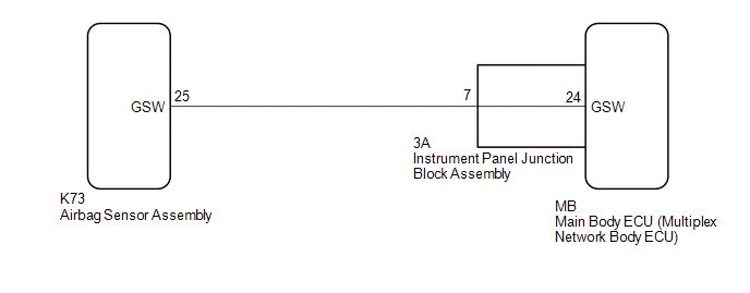
CAUTION / NOTICE / HINT
NOTICE:
- After turning the ignition switch off, waiting time may be required before disconnecting the cable from the negative (-) battery terminal. Therefore, make sure to read the disconnecting the cable from the negative (-) battery terminal notices before proceeding with work.
Click here
.gif)
- Before replacing the main body ECU (multiplex network body ECU), refer to Registration.*
Click here
*: w/ Smart Key System
PROCEDURE
|
1. | CHECK DTC OUTPUT |
(a) Clear the DTCs.
Body Electrical > Main Body > Clear DTCs(b) Recheck for DTCs.
Body Electrical > Main Body > Trouble CodesOK:
DTC B1243 is not output.
| OK | .gif) | USE SIMULATION METHOD TO CHECK
|
|
.gif)
| 2. |
CHECK MAIN BODY ECU (MULTIPLEX NETWORK BODY ECU) (GSW VOLTAGE) |
(a) Disconnect the cable from the negative (-) battery terminal.
CAUTION:
Wait at least 90 seconds after disconnecting the cable from the negative (-) battery terminal to disable the SRS system.
NOTICE:
Turning the ignition switch to ON with the airbag sensor assembly connector disconnected causes other DTCs to be stored. Clear the DTCs after performing this inspection.
(b) Disconnect the K73 airbag sensor assembly connector.
(c) Connect the cable to the negative (-) battery terminal.
| (d) Measure the voltage according to the value(s) in the table below. Standard Voltage:
|
|
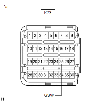
| NG | | GO TO STEP 5 |
|
| 3. |
REPLACE AIRBAG SENSOR ASSEMBLY |
(a) Disconnect the cable from the negative (-) battery terminal.
CAUTION:
Wait at least 90 seconds after disconnecting the cable from the negative (-) battery terminal to disable the SRS system.
(b) Replace the airbag sensor assembly.
Click here
|
| 4. |
CHECK DTC OUTPUT |
(a) Clear the DTCs.
Body Electrical > Main Body > Clear DTCs(b) Recheck for DTCs.
Body Electrical > Main Body > Trouble CodesOK:
DTC B1243 is not output.
| OK | | END (AIRBAG SENSOR ASSEMBLY WAS DEFECTIVE) |
| NG | | REPLACE MAIN BODY ECU (MULTIPLEX NETWORK BODY ECU)
|
| 5. |
CHECK HARNESS AND CONNECTOR (AIRBAG SENSOR ASSEMBLY - INSTRUMENT PANEL JUNCTION BLOCK ASSEMBLY) |
(a) Disconnect the cable from the negative (-) battery terminal.
CAUTION:
Wait at least 90 seconds after disconnecting the cable from the negative (-) battery terminal to disable the SRS system.
(b) Disconnect the 3A instrument panel junction block assembly connector.
(c) Measure the resistance according to the value(s) in the table below.
Standard Resistance:
|
Tester Connection | Condition |
Specified Condition |
|---|---|---|
|
K73-25 (GSW) - 3A-7 | Always |
Below 1 ? |
|
3A-7 or K73-25 (GSW) - Body ground |
Always | 10 k? or higher |
| NG | | REPAIR OR REPLACE HARNESS OR CONNECTOR |
|
| 6. |
INSPECT INSTRUMENT PANEL JUNCTION BLOCK ASSEMBLY |
(a) Remove the instrument panel junction block assembly.
Click here
(b) Remove the main body ECU (multiplex network body ECU).
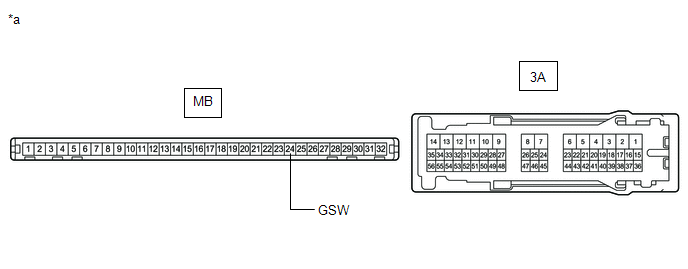
|
*a | Component without harness connected (Instrument Panel Junction Block Assembly) |
- | - |
(c) Measure the resistance according to the value(s) in the table below.
Standard Resistance:
|
Tester Connection | Condition |
Specified Condition |
|---|---|---|
|
MB-24 (GSW) - 3A-7 | Always |
Below 1 ? |
| OK | | REPLACE MAIN BODY ECU (MULTIPLEX NETWORK BODY ECU)
|
| NG | | REPLACE INSTRUMENT PANEL JUNCTION BLOCK ASSEMBLY
|
READ NEXT:
 All Doors LOCK/UNLOCK Functions do not Operate Via Door Key Cylinder
DESCRIPTION The main body ECU (multiplex network body ECU) receives switch signals from the door key lock and unlock switch (front door lock with motor assembly LH) and driver door key cylinder lock o
All Doors LOCK/UNLOCK Functions do not Operate Via Master Switch
DESCRIPTION The main body ECU (multiplex network body ECU) receives switch signals from the multiplex network master switch assembly and driver door key cylinder lock or unlock switch signals from the
All Doors LOCK/UNLOCK Functions do not Operate Via Door Control Switch
DESCRIPTION The main body ECU (multiplex network body ECU) receives switch signals from the door control switch assembly and activates the door lock motor on each door according to these signals. WIRI
SEE MORE:
Terminals Of Ecm
TERMINALS OF ECM ECM
HINT: The standard voltage and resistance of each ECM terminal is shown in the table below.
In the table, first follow the information under "Condition". Look under "Terminal No. (Symbol)" for the terminals to be inspected. The standard voltage or resistance between the ter
Communication Error from VSC to ECM Invalid Serial Data Received (P163081)
DESCRIPTION The skid control ECU (brake actuator assembly) sends signals such as brake request signals to the ECM. If an abnormal signal is detected, the ECM stores DTC P163081.
DTC No. Detection Item
DTC Detection Condition Trouble Area
DTC Output from
P163081 Communic
