Toyota Camry (XV70): Hazard Warning Switch Circuit
DESCRIPTION
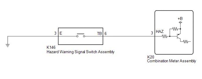
The combination meter assembly receives the hazard warning signal switch assembly on signal and controls the operation of the hazard warning lights.
WIRING DIAGRAM
CAUTION / NOTICE / HINT
NOTICE:
When replacing the combination meter assembly, always replace it with a new one. If a combination meter assembly which was installed to another vehicle is used, the information stored in it will not match the information from the vehicle and a DTC may be stored.
PROCEDURE
|
1. | READ VALUE USING TECHSTREAM |
(a) Connect the Techstream to the DLC3.
(b) Turn the ignition switch to ON.
(c) Turn the Techstream on.
(d) Enter the following menus: Body Electrical / Combination Meter / Data List.
(e) Read the Data List according to the display on the Techstream.
Body Electrical > Combination Meter > Data List|
Tester Display | Measurement Item |
Range | Normal Condition |
Diagnostic Note |
|---|---|---|---|---|
|
Hazard Flasher Switch |
Hazard warning signal switch signal |
OFF or ON | OFF: Hazard warning signal switch off ON: Hazard warning signal switch on |
- |
|
Tester Display |
|---|
|
Hazard Flasher Switch |
OK:
Normal conditions listed above are displayed.
| OK | .gif) |
PROCEED TO NEXT SUSPECTED AREA SHOWN IN PROBLEM SYMPTOMS TABLE
|
|
.gif)
|
2. | INSPECT HAZARD WARNING SIGNAL SWITCH ASSEMBLY |
(a) Remove the hazard warning signal switch assembly.
Click here
.gif)
(b) Inspect the hazard warning signal switch assembly.
Click here
| NG | |
REPLACE HAZARD WARNING SIGNAL SWITCH ASSEMBLY |
|
|
3. | CHECK HARNESS AND CONNECTOR (HAZARD WARNING SIGNAL SWITCH ASSEMBLY - COMBINATION METER ASSEMBLY AND BODY GROUND) |
(a) Disconnect the K20 combination meter assembly connector.
(b) Measure the resistance according to the value(s) in the table below.
Standard Resistance:
|
Tester Connection | Condition |
Specified Condition |
|---|---|---|
|
K146-6 (TB) - K20-3 (HAZ) |
Always | Below 1 Ω |
|
K146-6 (TB) or K20-3 (HAZ) - Body ground |
Always | 10 kΩ or higher |
|
K146-3 (E) - Body ground |
Always | Below 1 Ω |
| OK | |
REPLACE COMBINATION METER ASSEMBLY |
| NG | |
REPAIR OR REPLACE HARNESS OR CONNECTOR |
READ NEXT:
 LO-beam Headlight does not Illuminate
DESCRIPTION The main body ECU (multiplex network body ECU) controls the low beam headlights. WIRING DIAGRAM
CAUTION / NOTICE / HINT
NOTICE:
Inspect the fuses for circuits related to this
Parking Brake Switch Circuit
DESCRIPTION The main body ECU (multiplex network body ECU) detects the condition of the parking brake switch assembly. WIRING DIAGRAM
CAUTION / NOTICE / HINT
NOTICE: Before replacing the main b
Taillight Relay Circuit
DESCRIPTION The main body ECU (multiplex network body ECU) controls the operation of the TAIL relay. WIRING DIAGRAM
CAUTION / NOTICE / HINT
NOTICE:
Inspect the fuses for circuits related
SEE MORE:
Lost Communication With ECM/PCM "A" Missing Message (U010087,U010487,U012287)
DESCRIPTION The ECM communicates with each sensor and ECU via CAN communication.
If any malfunction is detected in a CAN communication circuit, one or more CAN communication system DTCs are stored.
DTC No. Detection Item
DTC Detection Condition Trouble Area
DTC Output from
Installation
INSTALLATION CAUTION / NOTICE / HINT
HINT:
Use the same procedure for the RH side and LH side.
The following procedure is for the LH side.
PROCEDURE 1. INSTALL FRONT DRIVE SHAFT HOLE SNAP RING
(a) Install a new front drive shaft hole snap ring. NOTICE: Face the end gap of the front d
