Toyota Camry (XV70): Parking Brake Switch Circuit
DESCRIPTION
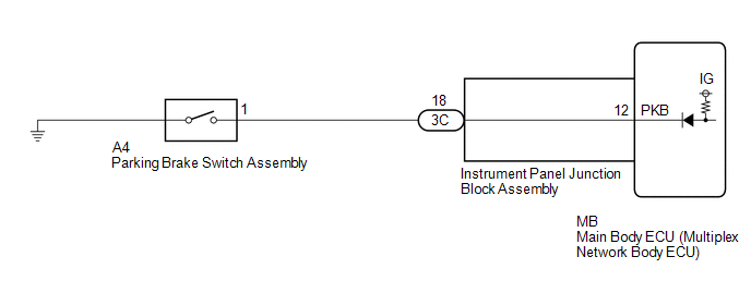
The main body ECU (multiplex network body ECU) detects the condition of the parking brake switch assembly.
WIRING DIAGRAM
CAUTION / NOTICE / HINT
NOTICE:
Before replacing the main body ECU (multiplex network body ECU), refer to Registration.*
Click here .gif)
- *: w/ Smart Key System
PROCEDURE
|
1. | READ VALUE USING TECHSTREAM |
(a) Connect the Techstream to the DLC3.
(b) Turn the ignition switch to ON.
(c) Turn the Techstream on.
(d) Enter the following menus: Body Electrical / Main Body / Data List.
(e) Read the Data List according to the display on the Techstream.
Body Electrical > Main Body > Data List|
Tester Display | Measurement Item |
Range | Normal Condition |
Diagnostic Note |
|---|---|---|---|---|
|
Parking Brake SW | Parking brake switch signal |
OFF or ON | OFF: Parking brake switch off ON: Parking brake switch on |
- |
|
Tester Display |
|---|
|
Parking Brake SW |
OK:
Normal conditions listed above are displayed.
| OK | .gif) |
PROCEED TO NEXT SUSPECTED AREA SHOWN IN PROBLEM SYMPTOMS TABLE
|
|
.gif)
|
2. | INSPECT PARKING BRAKE SWITCH ASSEMBLY |
(a) Remove the parking brake switch assembly.
Click here
(b) Inspect the parking brake switch assembly.
Click here
| NG | |
REPLACE PARKING BRAKE SWITCH ASSEMBLY
|
|
|
3. | CHECK HARNESS AND CONNECTOR (PARKING BRAKE SWITCH ASSEMBLY - INSTRUMENT PANEL JUNCTION BLOCK ASSEMBLY) |
(a) Disconnect the 3C instrument panel junction block assembly connector.
(b) Measure the resistance according to the value(s) in the table below.
Standard Resistance:
|
Tester Connection | Condition |
Specified Condition |
|---|---|---|
|
A4-1 - 3C-18 | Always |
Below 1 Ω |
|
A4-1 or 3C-18 - Body ground |
Always | 10 kΩ or higher |
| NG | |
REPAIR OR REPLACE HARNESS OR CONNECTOR |
|
|
4. | INSPECT INSTRUMENT PANEL JUNCTION BLOCK ASSEMBLY |
|
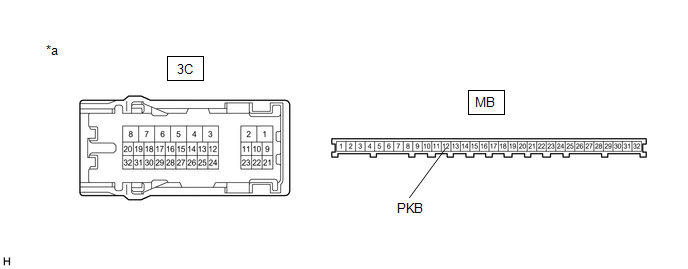
*a | Component without harness connected (Instrument Panel Junction Block Assembly) |
- | - |
(a) Remove the instrument panel junction block assembly.
Click here
(b) Remove the main body ECU (multiplex network body ECU) from the instrument panel junction block assembly.
(c) Measure the resistance according to the value(s) in the table below.
Standard Resistance:
|
Tester Connection | Condition |
Specified Condition |
|---|---|---|
|
3C-18 - MB-12 (PKB) |
Always | Below 1 Ω |
| OK | |
REPLACE MAIN BODY ECU (MULTIPLEX NETWORK BODY ECU)
|
| NG | |
REPLACE INSTRUMENT PANEL JUNCTION BLOCK ASSEMBLY
|
READ NEXT:
 Taillight Relay Circuit
DESCRIPTION The main body ECU (multiplex network body ECU) controls the operation of the TAIL relay. WIRING DIAGRAM
CAUTION / NOTICE / HINT
NOTICE:
Inspect the fuses for circuits related
High Beam Headlight Circuit
DESCRIPTION The main body ECU (multiplex network body ECU) controls the high beam headlights. WIRING DIAGRAM
CAUTION / NOTICE / HINT
NOTICE:
Inspect the fuses for circuits related to this
SEE MORE:
Outside Vehicle
OUTSIDE VEHICLE
These are maintenance and inspection items that are considered to be the owner's responsibility.
The owner can do them or they can have them done at a service center.
These items include those that should be checked on a daily basis, those that in most cases do not require s
Telematics Transceiver Disconnected (B15DB)
DESCRIPTION If the radio and display receiver assembly cannot detect the DCM (telematics transceiver) for a certain period of time (90 seconds) after the engine switch is turned on (ACC) and the radio and display receiver assembly confirms that the information is missing by checking past DCM (telema
