Toyota Camry (XV70): High Beam Headlight Circuit
DESCRIPTION
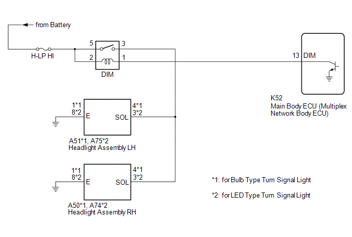
The main body ECU (multiplex network body ECU) controls the high beam headlights.
WIRING DIAGRAM
CAUTION / NOTICE / HINT
NOTICE:
- Inspect the fuses for circuits related to this system before performing the following procedure.
- Check the operation of the low beam headlights. If the low beam headlights do not operate normally, refer to Problem Symptoms Table.
Click here
.gif)
- Before replacing the main body ECU (multiplex network body ECU), refer to Registration.*
Click here
- *: w/ Smart Key System
PROCEDURE
|
1. | PERFORM ACTIVE TEST USING TECHSTREAM |
(a) Connect the Techstream to the DLC3.
(b) Turn the ignition switch to ON.
(c) Turn the Techstream on.
(d) Enter the following menus: Body Electrical / Main Body / Active Test.
(e) Perform the Active Test according to the display on the Techstream.
Body Electrical > Main Body > Active Test|
Tester Display | Measurement Item |
Control Range | Diagnostic Note |
|---|---|---|---|
|
Head Light Hi | High beam headlights |
OFF or ON | - |
|
Tester Display |
|---|
|
Head Light Hi |
OK:
High beam headlights illuminate.
| OK | .gif) |
PROCEED TO NEXT SUSPECTED AREA SHOWN IN PROBLEM SYMPTOMS TABLE
|
|
.gif)
|
2. | INSPECT DIM RELAY |
(a) Inspect the DIM relay.
Click here
| NG | |
REPLACE DIM RELAY |
|
|
3. | CHECK HARNESS AND CONNECTOR (POWER SOURCE - DIM RELAY) |
(a) Measure the voltage according to the value(s) in the table below.
Standard Voltage:
|
Tester Connection | Condition |
Specified Condition |
|---|---|---|
|
2 (DIM relay) - Body ground |
Always | 11 to 14 V |
|
5 (DIM relay) - Body ground |
Always | 11 to 14 V |
| NG | |
REPAIR OR REPLACE HARNESS OR CONNECTOR |
|
|
4. | CHECK HARNESS AND CONNECTOR (DIM RELAY - MAIN BODY ECU (MULTIPLEX NETWORK BODY ECU)) |
(a) Disconnect the K52 main body ECU (multiplex network body ECU) connector.
(b) Measure the resistance according to the value(s) in the table below.
Standard Resistance:
|
Tester Connection | Condition |
Specified Condition |
|---|---|---|
|
1 (DIM relay) - K52-13 (DIM) |
Always | Below 1 Ω |
|
1 (DIM relay) or K52-13 (DIM) - Body ground |
Always | 10 kΩ or higher |
| OK | |
REPLACE MAIN BODY ECU (MULTIPLEX NETWORK BODY ECU) |
| NG | |
REPAIR OR REPLACE HARNESS OR CONNECTOR |
READ NEXT:
 Components
COMPONENTS ILLUSTRATION
*A for LH Side
*B for RH Side
*1 LUGGAGE COMPARTMENT DOOR STRIKER COVER
*2 LUGGAGE COMPARTMENT TRIM INNER COVER LH
*3 LUG
Removal
REMOVAL CAUTION / NOTICE / HINT
HINT:
Use the same procedure for the RH side and LH side.
The following procedure is for the LH side.
PROCEDURE 1. REMOVE SPARE WHEEL COVER ASSEMBLY
SEE MORE:
Components
COMPONENTS ILLUSTRATION
*1 AIR CLEANER ASSEMBLY WITH AIR CLEANER HOSE
*2 COOL AIR INTAKE DUCT SEAL
*3 ECM
*4 INLET AIR CLEANER ASSEMBLY
*5 NO. 1 ECM BRACKET
*6 NO. 2 ECM BRACKET
*7 VACUUM HOSE
*8 NO. 1 FUEL VAPOR FEED HOSE
Stereo Jack Adapter Assembly
ComponentsCOMPONENTS ILLUSTRATION
*1 LOWER CENTER INSTRUMENT PANEL FINISH PANEL
*2 NO. 1 METER HOOD CLUSTER
*3 NO. 1 STEREO JACK ADAPTER ASSEMBLY
- - RemovalREMOVAL PROCEDURE
1. REMOVE NO. 1 METER HOOD CLUSTER Click here
2. REMOVE LOWER CENTER IN
