Toyota Camry (XV70): Taillight Relay Circuit
DESCRIPTION
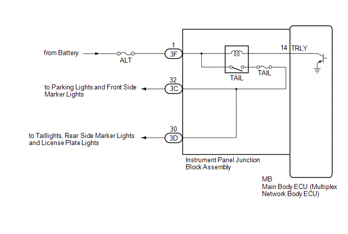
The main body ECU (multiplex network body ECU) controls the operation of the TAIL relay.
WIRING DIAGRAM
CAUTION / NOTICE / HINT
NOTICE:
- Inspect the fuses for circuits related to this system before performing the following procedure.
- Before replacing the main body ECU (multiplex network body ECU), refer to Registration.*
Click here
.gif)
- *: w/ Smart Key System
PROCEDURE
|
1. | PERFORM ACTIVE TEST USING TECHSTREAM |
(a) Connect the Techstream to the DLC3.
(b) Turn the ignition switch to ON.
(c) Turn the Techstream on.
(d) Enter the following menus: Body Electrical / Main Body / Active Test.
(e) Perform the Active Test according to the display on the Techstream.
Body Electrical > Main Body > Active Test|
Tester Display | Measurement Item |
Control Range | Diagnostic Note |
|---|---|---|---|
|
Taillight Relay | Taillight relay |
OFF or ON | - |
|
Tester Display |
|---|
|
Taillight Relay |
OK:
Taillights illuminate.
| OK | .gif) |
PROCEED TO NEXT SUSPECTED AREA SHOWN IN PROBLEM SYMPTOMS TABLE
|
|
.gif)
|
2. | CHECK HARNESS AND CONNECTOR (POWER SOURCE - INSTRUMENT PANEL JUNCTION BLOCK ASSEMBLY) |
(a) Disconnect the 3F instrument panel junction block assembly connector.
(b) Measure the voltage according to the value(s) in the table below.
Standard Voltage:
|
Tester Connection | Condition |
Specified Condition |
|---|---|---|
|
3F-1 - Body ground |
Always | 11 to 14 V |
| NG | |
REPAIR OR REPLACE HARNESS OR CONNECTOR |
|
|
3. | INSPECT INSTRUMENT PANEL JUNCTION BLOCK ASSEMBLY |
|
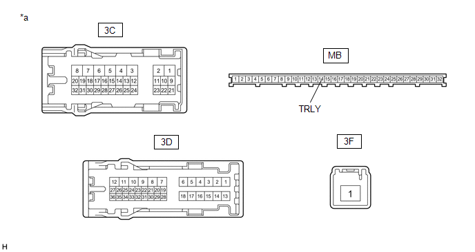
*a | Component without harness connected (Instrument Panel Junction Block Assembly) |
- | - |
(a) Remove the instrument panel junction block assembly.
Click here
(b) Remove the main body ECU (multiplex network body ECU) from the instrument panel junction block assembly.
(c) Connect a positive (+) lead from the battery to terminal 3F-1.
(d) Connect a negative (-) lead from the battery to terminal MB-14 (TRLY).
(e) Measure the voltage according to the value(s) in the table below.
Standard Voltage:
|
Tester Connection | Condition |
Specified Condition |
|---|---|---|
|
3C-32 - Battery negative (-) terminal |
Always | 11 to 14 V |
|
3D-30 - Battery negative (-) terminal |
Always | 11 to 14 V |
| OK | |
REPLACE MAIN BODY ECU (MULTIPLEX NETWORK BODY ECU)
|
| NG | |
REPLACE INSTRUMENT PANEL JUNCTION BLOCK ASSEMBLY
|
READ NEXT:
 High Beam Headlight Circuit
DESCRIPTION The main body ECU (multiplex network body ECU) controls the high beam headlights. WIRING DIAGRAM
CAUTION / NOTICE / HINT
NOTICE:
Inspect the fuses for circuits related to this
Components
COMPONENTS ILLUSTRATION
*A for LH Side
*B for RH Side
*1 LUGGAGE COMPARTMENT DOOR STRIKER COVER
*2 LUGGAGE COMPARTMENT TRIM INNER COVER LH
*3 LUG
SEE MORE:
Display - Intuitive parking assist
When the sensors detect an object, the following displays inform the
driver of the position and distance to the object.
Front corner sensor operation
Front center sensor operation
Rear corner sensor operation
Rear center sensor operation
Select to mute the buzzer
sounds.
■Mutin
Wiper Switch Signal Mismatch between LIN and Line (B1372)
DESCRIPTION Under normal operation, the windshield wiper motor assembly receives operation signals from the windshield wiper switch assembly via LIN communication.
The windshield wiper motor assembly and windshield wiper switch assembly are also connected via direct line in order to operate the f
