Toyota Camry (XV70): LO-beam Headlight does not Illuminate
DESCRIPTION
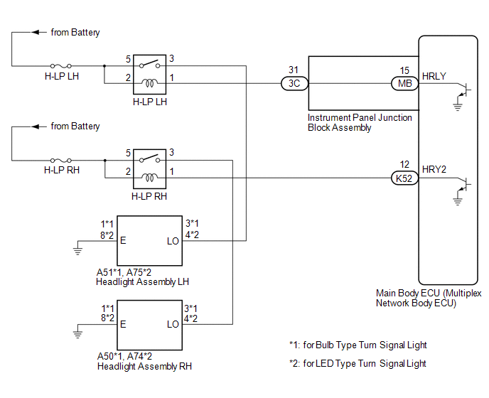
The main body ECU (multiplex network body ECU) controls the low beam headlights.
WIRING DIAGRAM
CAUTION / NOTICE / HINT
NOTICE:
- Inspect the fuses for circuits related to this system before performing the following procedure.
- Before replacing the main body ECU (multiplex network body ECU), refer to Registration.*
Click here
.gif)
- *: w/ Smart Key System
PROCEDURE
|
1. | PERFORM ACTIVE TEST USING TECHSTREAM |
(a) Connect the Techstream to the DLC3.
(b) Turn the ignition switch to ON.
(c) Turn the Techstream on.
(d) Enter the following menus: Body Electrical / Main Body / Active Test.
(e) Perform the Active Test according to the display on the Techstream.
Body Electrical > Main Body > Active Test|
Tester Display | Measurement Item |
Control Range | Diagnostic Note |
|---|---|---|---|
|
Headlight Relay | Low beam headlights |
OFF or ON | - |
|
Tester Display |
|---|
|
Headlight Relay |
OK:
Low beam headlights illuminate.
|
Result | Proceed to |
|---|---|
|
OK | A |
|
NG (for LH Side) |
B |
| NG (for RH Side) |
C |
| A | .gif) |
PROCEED TO NEXT SUSPECTED AREA SHOWN IN PROBLEM SYMPTOMS TABLE
|
| C | |
GO TO STEP 9 |
|
.gif)
|
2. | INSPECT HEADLIGHT ASSEMBLY LH (LO TERMINAL VOLTAGE) |
.png)
|
*A | for Bulb Type Turn Signal Light |
*B | for LED Type Turn Signal Light |
|
*a | Front view of wire harness connector (to Headlight Assembly LH) |
- | - |
(a) Disconnect the A51*1 or A75*2 headlight assembly LH connector.
- *1: for Bulb Type Turn Signal Light
- *2: for LED Type Turn Signal Light
(b) Measure the voltage according to the value(s) in the table below.
Standard Voltage:
for Bulb Type Turn Signal Light|
Tester Connection | Condition |
Specified Condition |
|---|---|---|
|
A51-3 (LO) - Body ground |
Light control switch in head position |
11 to 14 V |
|
Tester Connection | Condition |
Specified Condition |
|---|---|---|
|
A75-4 (LO) - Body ground |
Light control switch in head position |
11 to 14 V |
| NG | |
GO TO STEP 4 |
|
|
3. | CHECK HARNESS AND CONNECTOR (HEADLIGHT ASSEMBLY LH - BODY GROUND) |
(a) Measure the resistance according to the value(s) in the table below.
Standard Resistance:
for Bulb Type Turn Signal Light|
Tester Connection | Condition |
Specified Condition |
|---|---|---|
|
A51-1 (E) - Body ground |
Always | Below 1 Ω |
|
Tester Connection | Condition |
Specified Condition |
|---|---|---|
|
A75-8 (E) - Body ground |
Always | Below 1 Ω |
| OK | |
REPLACE HEADLIGHT ASSEMBLY LH |
| NG | |
REPAIR OR REPLACE HARNESS OR CONNECTOR |
|
4. | CHECK HARNESS AND CONNECTOR (H-LP LH RELAY - HEADLIGHT ASSEMBLY LH) |
(a) Remove the H-LP LH relay.
(b) Measure the resistance according to the value(s) in the table below.
Standard Resistance:
for Bulb Type Turn Signal Light|
Tester Connection | Condition |
Specified Condition |
|---|---|---|
|
3 (H-LP LH relay) - A51-3 (LO) |
Always | Below 1 Ω |
|
3 (H-LP LH relay) or A51-3 (LO) - Body ground |
Always | 10 kΩ or higher |
|
Tester Connection | Condition |
Specified Condition |
|---|---|---|
|
3 (H-LP LH relay) - A75-4 (LO) |
Always | Below 1 Ω |
|
3 (H-LP LH relay) or A75-4 (LO) - Body ground |
Always | 10 kΩ or higher |
| NG | |
REPAIR OR REPLACE HARNESS OR CONNECTOR |
|
|
5. | INSPECT H-LP LH RELAY |
(a) Inspect the H-LP LH relay.
Click here
| NG | |
REPLACE H-LP LH RELAY |
|
|
6. | CHECK HARNESS AND CONNECTOR (POWER SOURCE - H-LP LH RELAY) |
(a) Measure the voltage according to the value(s) in the table below.
Standard Voltage:
|
Tester Connection | Condition |
Specified Condition |
|---|---|---|
|
2 (H-LP LH relay) - Body ground |
Always | 11 to 14 V |
|
5 (H-LP LH relay) - Body ground |
Always | 11 to 14 V |
| NG | |
REPAIR OR REPLACE HARNESS OR CONNECTOR |
|
|
7. | CHECK HARNESS AND CONNECTOR (H-LP LH RELAY - INSTRUMENT PANEL JUNCTION BLOCK ASSEMBLY) |
(a) Disconnect the 3C instrument panel junction block assembly connector.
(b) Measure the resistance according to the value(s) in the table below.
Standard Resistance:
|
Tester Connection | Condition |
Specified Condition |
|---|---|---|
|
1 (H-LP LH relay) - 3C-31 |
Always | Below 1 Ω |
|
1 (H-LP LH relay) or 3C-31 - Body ground |
Always | 10 kΩ or higher |
| NG | |
REPAIR OR REPLACE HARNESS OR CONNECTOR |
|
|
8. | INSPECT INSTRUMENT PANEL JUNCTION BLOCK ASSEMBLY |
.png)
|
*a | Component without harness connected (Instrument Panel Junction Block Assembly) |
- | - |
(a) Remove the instrument panel junction block assembly.
Click here
(b) Remove the main body ECU (multiplex network body ECU) from the instrument panel junction block assembly.
(c) Measure the resistance according to the value(s) in the table below.
Standard Resistance:
|
Tester Connection | Condition |
Specified Condition |
|---|---|---|
|
3C-31 - MB-15 (HRLY) |
Always | Below 1 Ω |
| OK | |
REPLACE MAIN BODY ECU (MULTIPLEX NETWORK BODY ECU)
|
| NG | |
REPLACE INSTRUMENT PANEL JUNCTION BLOCK ASSEMBLY
|
|
9. | INSPECT HEADLIGHT ASSEMBLY RH (LO TERMINAL VOLTAGE) |
.png)
|
*A | for Bulb Type Turn Signal Light |
*B | for LED Type Turn Signal Light |
|
*a | Front view of wire harness connector (to Headlight Assembly RH) |
- | - |
(a) Disconnect the A50*1 or A74*2 headlight assembly RH connector.
- *1: for Bulb Type Turn Signal Light
- *2: for LED Type Turn Signal Light
(b) Measure the voltage according to the value(s) in the table below.
Standard Voltage:
for Bulb Type Turn Signal Light|
Tester Connection | Condition |
Specified Condition |
|---|---|---|
|
A50-3 (LO) - Body ground |
Light control switch in head position |
11 to 14 V |
|
Tester Connection | Condition |
Specified Condition |
|---|---|---|
|
A74-4 (LO) - Body ground |
Light control switch in head position |
11 to 14 V |
| NG | |
GO TO STEP 11 |
|
|
10. | CHECK HARNESS AND CONNECTOR (HEADLIGHT ASSEMBLY RH - BODY GROUND) |
(a) Measure the resistance according to the value(s) in the table below.
Standard Resistance:
for Bulb Type Turn Signal Light|
Tester Connection | Condition |
Specified Condition |
|---|---|---|
|
A50-1 (E) - Body ground |
Always | Below 1 Ω |
|
Tester Connection | Condition |
Specified Condition |
|---|---|---|
|
A74-8 (E) - Body ground |
Always | Below 1 Ω |
| OK | |
REPLACE HEADLIGHT ASSEMBLY RH |
| NG | |
REPAIR OR REPLACE HARNESS OR CONNECTOR |
|
11. | CHECK HARNESS AND CONNECTOR (H-LP RH RELAY - HEADLIGHT ASSEMBLY RH) |
(a) Remove the H-LP RH relay.
(b) Measure the resistance according to the value(s) in the table below.
Standard Resistance:
for Bulb Type Turn Signal Light|
Tester Connection | Condition |
Specified Condition |
|---|---|---|
|
3 (H-LP RH relay) - A50-3 (LO) |
Always | Below 1 Ω |
|
3 (H-LP RH relay) or A50-3 (LO) - Body ground |
Always | 10 kΩ or higher |
|
Tester Connection | Condition |
Specified Condition |
|---|---|---|
|
3 (H-LP RH relay) - A74-4 (LO) |
Always | Below 1 Ω |
|
3 (H-LP RH relay) or A74-4 (LO) - Body ground |
Always | 10 kΩ or higher |
| NG | |
REPAIR OR REPLACE HARNESS OR CONNECTOR |
|
|
12. | INSPECT H-LP RH RELAY |
(a) Inspect the H-LP RH relay.
Click here
| NG | |
REPLACE H-LP RH RELAY |
|
|
13. | CHECK HARNESS AND CONNECTOR (POWER SOURCE - H-LP RH RELAY) |
(a) Measure the voltage according to the value(s) in the table below.
Standard Voltage:
|
Tester Connection | Condition |
Specified Condition |
|---|---|---|
|
2 (H-LP RH relay) - Body ground |
Always | 11 to 14 V |
|
5 (H-LP RH relay) - Body ground |
Always | 11 to 14 V |
| NG | |
REPAIR OR REPLACE HARNESS OR CONNECTOR |
|
|
14. | CHECK HARNESS AND CONNECTOR (H-LP RH RELAY - MAIN BODY ECU (MULTIPLEX NETWORK BODY ECU)) |
(a) Disconnect the K52 main body ECU (multiplex network body ECU) connector.
(b) Measure the resistance according to the value(s) in the table below.
Standard Resistance:
|
Tester Connection | Condition |
Specified Condition |
|---|---|---|
|
1 (H-LP RH relay) - K52-12 (HRY2) |
Always | Below 1 Ω |
|
1 (H-LP RH relay) or K52-12 (HRY2) - Body ground |
Always | 10 kΩ or higher |
| OK | |
REPLACE MAIN BODY ECU (MULTIPLEX NETWORK BODY ECU)
|
| NG | |
REPAIR OR REPLACE HARNESS OR CONNECTOR |
READ NEXT:
 Parking Brake Switch Circuit
DESCRIPTION The main body ECU (multiplex network body ECU) detects the condition of the parking brake switch assembly. WIRING DIAGRAM
CAUTION / NOTICE / HINT
NOTICE: Before replacing the main b
Taillight Relay Circuit
DESCRIPTION The main body ECU (multiplex network body ECU) controls the operation of the TAIL relay. WIRING DIAGRAM
CAUTION / NOTICE / HINT
NOTICE:
Inspect the fuses for circuits related
High Beam Headlight Circuit
DESCRIPTION The main body ECU (multiplex network body ECU) controls the high beam headlights. WIRING DIAGRAM
CAUTION / NOTICE / HINT
NOTICE:
Inspect the fuses for circuits related to this
SEE MORE:
ECM Communication (C124A00)
DESCRIPTION If the vehicle information stored by the skid control ECU (brake actuator assembly) does not match that sent from the ECM or a new skid control ECU (brake actuator assembly) is installed and the vehicle information has not been stored, this DTC is stored.
DTC No. Detection Item
On-vehicle Inspection
ON-VEHICLE INSPECTION CAUTION / NOTICE / HINT
NOTICE: If the battery is weak or if the engine is difficult to start, recharge the battery and perform inspections again before returning the vehicle to the customer. PROCEDURE
1. CHECK BATTERY CONDITION (a) Check the battery for damage or deformati
