Toyota Camry (XV70): High Mounted Stop Light Assembly
Components
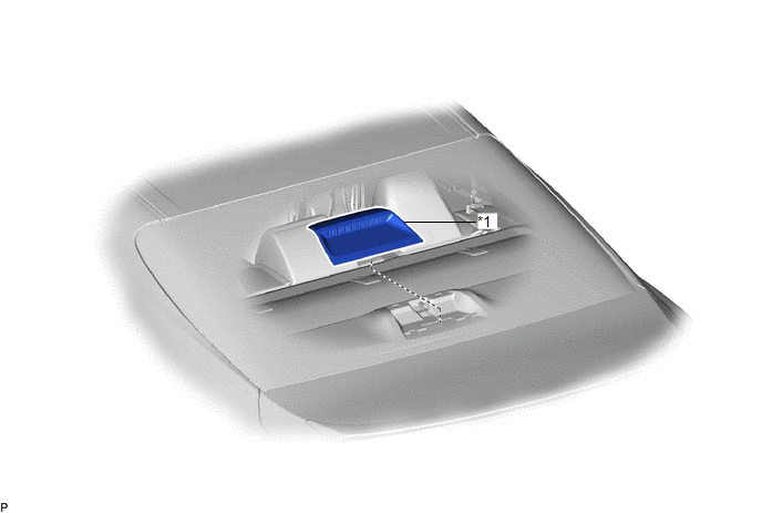
COMPONENTS
ILLUSTRATION
|
*1 | CENTER STOP LIGHT SET |
- | - |
Removal
REMOVAL
PROCEDURE
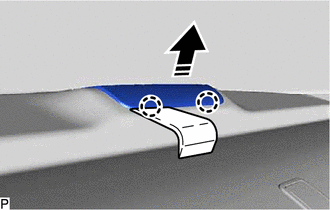
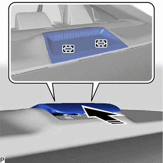
1. REMOVE CENTER STOP LIGHT SET
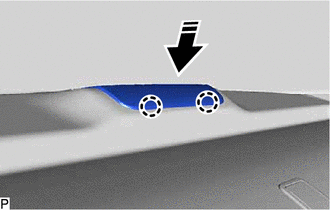
(a) Using a moulding remover, disengage the 2 claws as shown in the illustration.
.png) |
Remove in this Direction |
| (b) Disconnect the connector. |
|
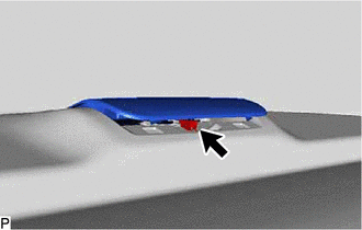
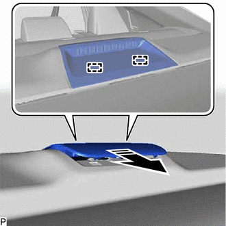
(c) Disengage the 2 guides as shown in the illustration to remove the center stop light set.
|
|
Remove in this Direction |
Inspection
INSPECTION
PROCEDURE
1. INSPECT CENTER STOP LIGHT SET
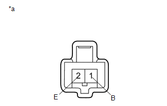
|
*a | Component without harness connected (Center Stop Light Set) |
(a) Apply battery voltage to the center stop light set and check that the light illuminates.
OK:
|
Condition | Specified Condition |
|---|---|
|
Battery positive (+) → Terminal 1 (B) Battery negative (-) → Terminal 2 (E) |
Center stop light illuminates |
If the result is not as specified, replace the center stop light set.
Installation
INSTALLATION
PROCEDURE
1. INSTALL CENTER STOP LIGHT SET
(a) Engage the 2 guides as shown in the illustration.
.png) |
Install in this Direction |
(b) Connect the connector.
(c) Engage the 2 claws as shown in the illustration to install the center stop light set.
|
|
Install in this Direction |
READ NEXT:
 License Plate Light Assembly
ComponentsCOMPONENTS ILLUSTRATION
*1 LICENSE PLATE LIGHT ASSEMBLY
*2 LUGGAGE COMPARTMENT DOOR COVER
*3 NO. 3 LUGGAGE COMPARTMENT DOOR OUTSIDE GARNISH
- -
Precaution
PRECAUTION PRECAUTION FOR DISCONNECTING CABLE FROM NEGATIVE BATTERY TERMINAL
NOTICE: When disconnecting the cable from the negative (-) battery terminal, initialize the following systems after the
SEE MORE:
Removal
REMOVAL CAUTION / NOTICE / HINT
The necessary procedures (adjustment, calibration, initialization or registration) that must be performed after parts are removed and installed, or replaced during sliding roof housing removal/installation are shown below. Necessary Procedures After Parts Removed/I
Components
COMPONENTS ILLUSTRATION
*A for A25A-FKS
*B for 2GR-FKS
*1 FRONT FENDER APRON SEAL LH
*2 FRONT FLOOR COVER LH
*3 FRONT WHEEL OPENING EXTENSION PAD LH
*4 FRONT WHEEL OPENING EXTENSION PAD RH
*5 NO. 1 ENGINE UNDER COVER
*6 NO. 2
