Toyota Camry (XV70): Inspection
INSPECTION
PROCEDURE
1. INSPECT BRAKE CYLINDER AND PISTON
(a) Check the front disc brake cylinder bore and front disc brake piston for rust and scoring. If necessary, replace the front disc brake cylinder assembly and front disc brake piston.
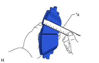
2. INSPECT PAD LINING THICKNESS
| (a) Using a ruler, measure the front disc brake pad lining thickness. Standard Thickness: 11.0 mm (0.433 in.) Minimum Thickness: 1.0 mm (0.0394 in.) HINT:
|
|
3. INSPECT FRONT DISC BRAKE PAD SUPPORT PLATE
(a) Make sure that the front disc brake pad support plates have sufficient rebound, no deformation, cracks or wear, and that all rust and dirt is cleaned off. If necessary, replace the front disc brake pad support plates.
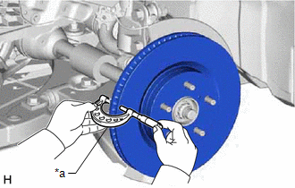
4. INSPECT DISC THICKNESS
| (a) Using a micrometer, measure the front disc thickness. Standard Thickness: 28.0 mm (1.10 in.) Minimum Thickness: 25.0 mm (0.984 in.) HINT: If the front disc thickness is less than the minimum thickness, replace the front disc. |
|
5. INSPECT DISC RUNOUT
(a) Inspect the front axle hub bearing looseness and front axle hub runout.
Click here .gif)
(b) Temporarily install the front disc with the 5 hub nuts.
Torque:
103 N
READ NEXT:
 Reassembly
REASSEMBLY CAUTION / NOTICE / HINT PROCEDURE
1. TEMPORARILY TIGHTEN FRONT DISC BRAKE BLEEDER PLUG (a) Temporarily install the front disc brake bleeder plug to the front disc brake cylinder.
HINT:
Installation
INSTALLATION CAUTION / NOTICE / HINT
NOTICE:
Immediately after installing the brake pads, the braking performance may be reduced. Always perform a road test in a safe place while paying attentio
SEE MORE:
Components
COMPONENTS ILLUSTRATION
*A except Panoramic Moon Roof
- -
*1 TELEPHONE AND GPS ANTENNA ASSEMBLY
*2 TELEPHONE AND GPS ANTENNA ASSEMBLY WITH COVER
*3 COVER
*4 WASHER AND HOLDER
*5 SEAL
*6 TELEPHONE ANTENNA HOUSING
Power Window Motor Malfunction (B2311)
DESCRIPTION The power window regulator motor assemblies are operated by the multiplex network master switch assembly, power window regulator switch assembly or rear power window regulator switch assemblies. The power window regulator motor assemblies have motor, regulator and ECU functions.
This
