Toyota Camry (XV70): Inspection
INSPECTION
PROCEDURE
1. INSPECT MASS AIR FLOW METER SUB-ASSEMBLY
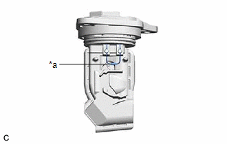
| (a) Perform a visual check for any foreign matter on the intake air temperature sensor (thermistor) of the mass air flow meter sub-assembly shown in the illustration. OK: There is no foreign matter. If the result is not as specified, clean the intake air temperature sensor (thermistor). |
|
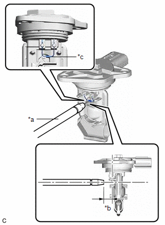
(b) Clean the intake air temperature sensor (thermistor).
NOTICE:
- Do not contact the mass air flow meter sub-assembly with the nozzle of the air blow gun.
- Do not insert the nozzle of the air blow gun into the intake air temperature sensor (thermistor) area.
|
*a | Air Blow Gun |
|
*b | 10 mm (0.394 in.) |
|
*c | Intake Air Temperature Sensor (Thermistor) |
| (1) Using an air blow gun, clean the intake air temperature sensor (thermistor) area of the mass air flow meter sub-assembly by applying approximately 10 intermittent bursts of air to the intake air temperature sensor (thermistor) area at a pressure of approximately 392 to 981 kPa (4.0 to 10.0 kgf/cm2, 57 to 142 psi). HINT: After performing cleaning, read the value of Data List item "Mass Air Flow Sensor" using the Techstream and if the value is not as specified, replace the mass air flow meter sub-assembly. |
|
.png)
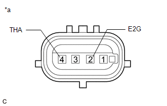
| (c) Check the intake air temperature sensor (thermistor) resistance. (1) Measure the resistance according to the value(s) in the table below. Standard Resistance:
If the result is not as specified, replace the mass air flow meter sub-assembly. |
|
READ NEXT:
 Installation
INSTALLATION PROCEDURE 1. INSTALL MASS AIR FLOW METER SUB-ASSEMBLY
HINT: Perform "Inspection After Repair" after replacing the mass air flow meter sub-assembly.
Click here
(a) Install the
Relay
On-vehicle InspectionON-VEHICLE INSPECTION PROCEDURE
1. INSPECT NO. 1 ELECTRONIC FUEL INJECTION MAIN RELAY (EFI-MAIN NO. 1)
(a) Measure the resistance according to the value(s) in the table be
SEE MORE:
Inspection
INSPECTION CAUTION / NOTICE / HINT
CAUTION: Ensure that fingers or articles of clothing do not get caught in moving parts when performing this test. PROCEDURE
1. INSPECT WINDSHIELD WIPER MOTOR ASSEMBLY
(a) Check the HI operation. (1) Connect a positive (+) lead from the battery to termi
Inspection
INSPECTION PROCEDURE 1. INSPECT ENGINE OIL PRESSURE SWITCH ASSEMBLY
(a) Disengage the clamp to disconnect the wire harness protector.
*1 Wire Harness Protector
(b) Disconnect the engine oil pressure switch assembly connector. (c) Start the engine.
