Toyota Camry (XV70): Inspection
INSPECTION
PROCEDURE
1. INSPECT FUEL PRESSURE SENSOR (FUEL DELIVERY PIPE WITH SENSOR ASSEMBLY LH)
NOTICE:
- Do not remove the fuel pressure sensor from the fuel delivery pipe with sensor assembly LH.
- If the fuel pressure sensor is removed, replace the fuel pressure sensor (fuel delivery pipe with sensor assembly LH) with a new one.
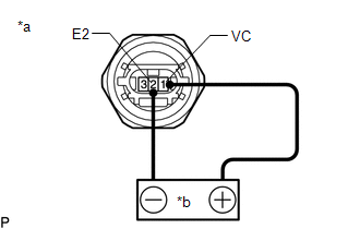
(a) Check the fuel pressure sensor output voltage.
| (1) Apply 5 V between terminals 1 (VC) and 2 (E2). NOTICE:
HINT: If a stable power supply is not available, connect 4 nickel-metal hydride batteries (1.2 V each) or equivalent in series. |
|
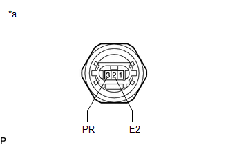
| (2) Measure the voltage according to the value(s) in the table below. Standard Voltage:
*: The output voltage changes depending on the voltage applied to the terminals. If the result is not as specified, replace the fuel pressure sensor (fuel delivery pipe with sensor assembly LH). |
|
READ NEXT:
 Installation
INSTALLATION PROCEDURE 1. INSTALL FUEL PIPE PLUG SUB-ASSEMBLY
(a) Install a new O-ring, No. 1 fuel injector back-up ring, No. 2 fuel injector back-up ring and No. 3 fuel injector back-up ring to the
Inspection
INSPECTION PROCEDURE 1. INSPECT FUEL PRESSURE SENSOR (FUEL DELIVERY PIPE WITH SENSOR ASSEMBLY LH)
NOTICE:
Do not remove the fuel pressure sensor from the fuel delivery pipe with sensor assembly
Installation
INSTALLATION PROCEDURE 1. INSTALL FUEL PIPE PLUG SUB-ASSEMBLY
(a) Install a new O-ring, No. 1 fuel injector back-up ring, No. 2 fuel injector back-up ring and No. 3 fuel injector back-up ring to the
SEE MORE:
Utility
UTILITY NOTICE: When the forward recognition camera has been replaced due to a lane tracing assist system malfunction, failure to adjust the forward recognition camera optical axis may affect all the systems using the forward recognition camera.
HINT: Forward recognition camera axis alignment can
Reassembly
REASSEMBLY CAUTION / NOTICE / HINT
HINT:
Use the same procedure for the RH side and LH side.
The following procedure is for the LH side.
PROCEDURE 1. INSTALL SIDE TURN SIGNAL LIGHT ASSEMBLY (w/ Side Turn Signal Light)
Click here 2. INSTALL NO. 2 OUTER MIRROR COVER (for Type A
