Toyota Camry (XV70): Inspection
INSPECTION
PROCEDURE
1. INSPECT WATER INLET WITH THERMOSTAT SUB-ASSEMBLY
CAUTION:
- Do not put your hands into the water that has been heated for the inspection.
- Touching the heated water could result in burns.
.png)
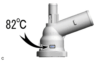
HINT:
The valve opening temperature is inscribed on the water inlet with thermostat sub-assembly.
(a) Immerse the water inlet with thermostat sub-assembly in water and then gradually heat the water.
NOTICE:
Do not allow any water to come into contact with the connector of the water inlet with thermostat sub-assembly.
(b) Check that the valve of the water inlet with thermostat sub-assembly opens at the specified temperature.
Standard Valve Opening Temperature:
80 to 84°C (176 to 183°F)
If the result is not as specified, replace the water inlet with thermostat sub-assembly.
| (c) Check the valve lift. Standard Valve Lift: 8.0 mm (0.315 in.) or more at 95°C (203°F) If the result is not as specified, replace the water inlet with thermostat sub-assembly. |
|

(d) Check that the valve is fully closed when the water inlet with thermostat sub-assembly is at low temperatures (below 72 °C (162 °F)).
If it is not fully closed, replace the water inlet with thermostat sub-assembly.
(e) Measure the resistance according to the value(s) in the table below.
Standard Resistance:
|
Tester Connection | Condition |
Specified Condition |
|---|---|---|
|
1 - 2 | Always |
10.6 to 14.2 Ω |
If the result is not as specified, replace the water inlet with thermostat sub-assembly.
READ NEXT:
 Installation
INSTALLATION CAUTION / NOTICE / HINT
NOTICE: This procedure includes the installation of small-head bolts. Refer to Small-Head Bolts of Basic Repair Hint to identify the small-head bolts.
Click he
Water Pump
ComponentsCOMPONENTS ILLUSTRATION
*1 ENGINE WATER PUMP ASSEMBLY (WATER INLET HOUSING)
*2 GASKET
N*m (kgf*cm, ft.*lbf): Specified torque
● Non-reusable
SEE MORE:
Internal Control Module Throttle Position Performance Internal Electronic Failure (P060E49,P061E49)
MONITOR DESCRIPTION The ECM monitors the signals received from the No. 1 throttle position sensor and stop light switch assembly. As the ECM monitors the STP signal of the stop light switch assembly and the VTA1 signal of the No. 1 throttle position sensor, if these signals do not correlate, a DTC w
Thermostat Heater Control Circuit Short to Ground or Open (P059714)
DESCRIPTION Refer to DTC P059712. Click here
DTC No. Detection Item
DTC Detection Condition Trouble Area
MIL Memory
Note P059714
Thermostat Heater Control Circuit Short to Ground or Open
Open or short in thermostat heater circuit and power supply circui
