
Toyota Camry (XV70): Installation
Toyota Camry Repair Manual XV70 (2018-2024) / Brake / Brake (front) / Front Brake (for 2-pot Caliper) / Installation
INSTALLATION
CAUTION / NOTICE / HINT
NOTICE:
- Immediately after installing the front disc brake pads, the braking performance may be reduced. Always perform a road test in a safe place while paying attention to the surroundings.
- After replacing the front disc brake pads, always perform a road test to check the braking performance and check for vibrations.
HINT:
- Use the same procedure for the RH side and LH side.
- The following procedure is for the LH side.
PROCEDURE
1. INSTALL FRONT DISC
| (a) Align the matchmarks of the front disc and front axle hub sub-assembly, and install the front disc. NOTICE: When replacing the front disc with a new one, select the installation position where the front disc has minimal runout. |
|
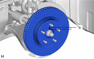
2. INSTALL FRONT DISC BRAKE CYLINDER MOUNTING
(a) Install the front disc brake cylinder mounting to the steering knuckle with the 2 bolts.
Torque:
107 N
READ NEXT:
 Front Brake Flexible Hose
ComponentsCOMPONENTS ILLUSTRATION
*1 FRONT FLEXIBLE HOSE
*2 GASKET
*3 BRAKE LINE
*4 FRONT SPEED SENSOR
*5 UNION BOLT
- -
Tighteni
Front Disc Brake Pad
ComponentsCOMPONENTS ILLUSTRATION
*1 FRONT DISC BRAKE ANTI-SQUEAL SHIM KIT
*2 FRONT DISC BRAKE PAD
*3 FRONT DISC BRAKE CYLINDER ASSEMBLY
*4 FRONT DISC BRAKE PAD W
Front Disc Brake Pad (for 2-pot Caliper)
ComponentsCOMPONENTS ILLUSTRATION
*1 FRONT DISC BRAKE ANTI-SQUEAL SHIM KIT
*2 FRONT DISC BRAKE PAD
*3 FRONT DISC BRAKE CYLINDER ASSEMBLY
*4 FRONT DISC BRAKE PAD W
SEE MORE:
Problem Symptoms Table
PROBLEM SYMPTOMS TABLE
HINT:
Use the table below to help determine the cause of problem symptoms. If multiple suspected areas are listed, the potential causes of the symptoms are listed in order of probability in the "Suspected Area" column of the table. Check each symptom by checking the susp
Disassembly
DISASSEMBLY PROCEDURE 1. REMOVE INSTRUMENT PANEL PASSENGER AIRBAG ASSEMBLY
Click here 2. REMOVE NO. 1 SIDE DEFROSTER NOZZLE DUCT
(a) Remove the screw <C>.
Remove in this Direction (b) Disengage the 2 guides as shown in the illustration.
(c) Disengage the claw to remove the
© 2023-2026 Copyright www.tocamry.com
