Toyota Camry (XV70): Installation
INSTALLATION
PROCEDURE
1. INSTALL ENGINE OIL PRESSURE SWITCH ASSEMBLY
| (a) Apply adhesive to 2 or 3 threads of the engine oil pressure switch assembly. Adhesive: Toyota Genuine Adhesive 1344, Three Bond 1344 or equivalent NOTICE:
|
|
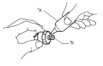
(b) Using a 24 mm deep socket wrench, install the engine oil pressure switch assembly.
Torque:
15 N·m {153 kgf·cm, 11 ft·lbf}
NOTICE:
Do not start the engine for at least 1 hour after installation.
(c) Connect the engine oil pressure switch assembly connector.
(d) Engage the clamp to connect the wire harness protector.
2. ADD ENGINE OIL
Click here .gif)
3. CHECK ENGINE OIL LEVEL
Click here
4. INSPECT FOR OIL LEAK
Click here
5. INSTALL FRONT FENDER APRON SEAL RH
Click here
READ NEXT:
 Components
COMPONENTS ILLUSTRATION
*1 ENGINE OIL PRESSURE SWITCH ASSEMBLY
*2 FRONT FENDER APRON SEAL RH
*3 WIRE HARNESS PROTECTOR
- -
N*m (kgf*cm, ft*lbf): Sp
Removal
REMOVAL PROCEDURE 1. REMOVE FRONT FENDER APRON SEAL RH
Click here
2. DRAIN ENGINE OIL Click here
3. REMOVE ENGINE OIL PRESSURE SWITCH ASSEMBLY
(a) Disengage the clamp to disco
Inspection
INSPECTION PROCEDURE 1. INSPECT ENGINE OIL PRESSURE SWITCH ASSEMBLY
(a) Disengage the clamp to disconnect the wire harness protector.
*1 Wire Harness Protector
SEE MORE:
Right Rear Wheel ABS Hold Solenoid Control Circuit Short to Battery (C12E712,...,C12F249)
DESCRIPTION The ABS solenoid relay and solenoid valves are built into the brake actuator assembly.
The rear solenoid valve RH controls the brake fluid pressure of the rear wheel cylinder RH of the vehicle.
When this DTC is stored, the fail-safe function operates and the ABS solenoid relay is tur
Light bulbs
You may replace the following bulbs yourself. The difficulty level
of replacement varies depending on the bulb. If necessary bulb
replacement seems difficult to perform, contact your Toyota
dealer.
For more information about replacing other light bulbs, contact
your Toyota dealer.
Preparing
© 2023-2026 Copyright www.tocamry.com
