
Toyota Camry (XV70): On-vehicle Inspection
ON-VEHICLE INSPECTION
PROCEDURE
1. INSPECT WINDSHIELD WIPER MOTOR ASSEMBLY
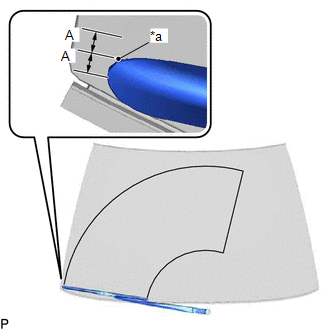
| (a) for RH Side: (1) Operate the windshield wiper motor assembly. (2) Stop the windshield wiper motor assembly operation. (3) Check the automatic stop (park) position. HINT: After the front wiper motor is stopped, check the automatic stop position after lifting the wiper blade 2 times. Standard Clearance:
OK: The front wiper stops at the position shown in the illustration. |
|
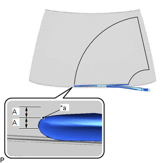
| (b) for LH Side: (1) Operate the windshield wiper motor assembly. (2) Stop the windshield wiper motor assembly operation. (3) Check the automatic stop (park) position. HINT: After the front wiper motor is stopped, check the automatic stop position after lifting the wiper blade 2 times. Standard Clearance:
OK: The front wiper stops at the position shown in the illustration. |
|
READ NEXT:
 Removal
REMOVAL CAUTION / NOTICE / HINT
NOTICE: Make sure to hold the front wiper arm while lifting it as lifting the front wiper arm by the front wiper blade may damage or deform the front wiper blade. PR
Inspection
INSPECTION CAUTION / NOTICE / HINT
CAUTION: Ensure that fingers or articles of clothing do not get caught in moving parts when performing this test. PROCEDURE
1. INSPECT WINDSHIELD WIPER MOTOR A
Installation
INSTALLATION CAUTION / NOTICE / HINT
NOTICE: Make sure to hold the front wiper arm while lifting it as lifting the front wiper arm by the front wiper blade may damage or deform the front wiper blad
SEE MORE:
Freeze Frame Data
FREEZE FRAME DATA FREEZE FRAME DATA
HINT:
When a DTC is stored, the freeze frame data stores the current vehicle (sensor) state as.
The freeze frame data cannot be cleared or updated until the recorded DTCs are cleared.
Chassis > Brake
Tester Display Measurement Item
R
Disassembly
DISASSEMBLY PROCEDURE 1. REMOVE OIL PUMP RELIEF VALVE
(a) Using a 27 mm socket wrench, remove the oil pump relief valve plug from the oil pump cover.
(b) Remove the oil pump relief valve spring and oil pump relief valve from the valve hole.
2. REMOVE OIL PUMP COVER
