Toyota Camry (XV70): Panoramic Moon Roof System does not Operate
DESCRIPTION
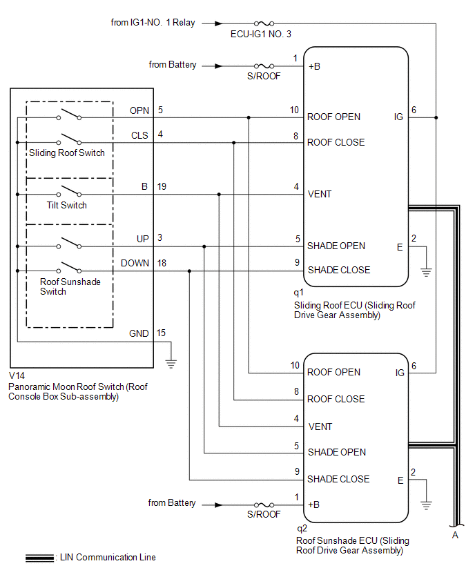
The sliding roof ECU (sliding roof drive gear assembly) and roof sunshade ECU (sliding roof drive gear assembly) receive each other's position information from the main body ECU (multiplex network body ECU) via LIN communication.
The sliding roof ECU (sliding roof drive gear assembly) and roof sunshade ECU (sliding roof drive gear assembly) receive signals from each switch, and operate their built-in motors.
For the linked functions of the sliding roof and roof sunshade refer to Operation Check.
Click here .gif)
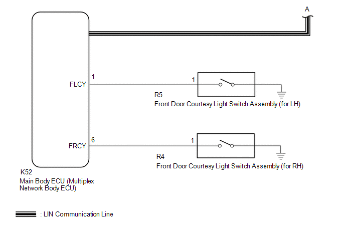
WIRING DIAGRAM
CAUTION / NOTICE / HINT
NOTICE:
- Inspect the fuses for circuits related to this system before performing the following procedure.
- The sliding roof auto operation function can be customized. Make sure that the function is set to ON.
Click here
- If the sliding roof ECU (sliding roof drive gear assembly) or roof sunshade ECU (sliding roof drive gear assembly) is removed and reinstalled or replaced, the sliding roof ECU (sliding roof drive gear assembly) or roof sunshade ECU (sliding roof drive gear assembly) must be initialized.
Click here
- The panoramic moon roof system uses the LIN communication systems. First, confirm that there are no malfunctions in the and LIN communication systems. Refer to How to Proceed with Troubleshooting.
Click here
- If a sliding roof ECU (sliding roof drive gear assembly) DTC is output,perform troubleshooting for the DTC first.
Click here
PROCEDURE
|
1. | CHECK FOR DTC (MAIN BODY) |
(a) Clear the DTCs.
Click here
(b) Check for DTCs.
Click here
OK:
DTCs B1273 and B2329 are not output.
| NG | .gif) |
GO TO LIN COMMUNICATION SYSTEM (Proceed to How to Proceed with Troubleshooting) |
|
.gif)
|
2. | CHECK FOR DTC (SLIDING ROOF AND SLIDING SUNSHADE) |
(a) Clear the DTCs.
Click here
(b) Check for DTCs.
Click here
OK:
DTCs B2341 and B2344 are not output.
| NG | |
GO TO DIAGNOSTIC TROUBLE CODE CHART |
|
|
3. | CHECK POWER WINDOW CONTROL SYSTEM |
(a) Check the power window control system operates normally.
Click here
OK:
The power window control system operates normally.
| NG | |
GO TO POWER WINDOW CONTROL SYSTEM |
|
|
4. | PERFORM ACTIVE TEST USING TECHSTREAM (SLIDING ROOF) |
(a) Connect the Techstream to the DLC3.
(b) Turn the engine switch on (IG).
(c) Turn the Techstream on.
(d) Enter the following menus: Body Electrical / Sliding Roof / Active Test.
(e) Perform the Active Test according to the display on the Techstream.
Body Electrical > Sliding Roof > Active Test|
Tester Display | Measurement Item |
Control Range | Diagnostic Note |
|---|---|---|---|
|
Slide Roof | Operate sliding roof motor |
OFF / Opn/Dwn / Clos/Up |
- |
|
Tester Display |
|---|
|
Slide Roof |
OK:
Slide roof is operated using Techstream.
| NG | |
GO TO STEP 13 |
|
|
5. | READ VALUE USING TECHSTREAM (SLIDING ROOF) |
(a) Connect the Techstream to the DLC3.
(b) Turn the engine switch on (IG).
(c) Turn the Techstream on.
(d) Enter the following menus: Body Electrical / Sliding Roof / Data List.
(e) Read the Data List according to the display on the Techstream.
Body Electrical > Sliding Roof > Data List|
Tester Display | Measurement Item |
Range | Normal Condition |
Diagnostic Note |
|---|---|---|---|---|
|
Vent Switch | Tilt switch signal |
OFF or ON | OFF: Tilt switch not pressed ON: Tilt switch pressed |
- |
| Roof Open Switch |
Sliding roof open switch signal |
OFF or ON | OFF: Sliding roof switch not slid backward ON: Sliding roof switch slid backward |
- |
| Roof Close Switch |
Sliding roof close switch signal |
OFF or ON | OFF: Sliding roof switch not slid forward ON: Sliding roof switch slid forward |
- |
| Shade Close Switch |
Roof sunshade close switch signal |
OFF or ON | OFF: Roof sunshade switch not slid forward ON: Roof sunshade switch slid forward |
- |
| Shade Open Switch |
Roof sunshade open switch signal |
OFF or ON | OFF: Roof sunshade switch not slid backward ON: Roof sunshade switch slid backward |
- |
|
Tester Display |
|---|
|
Vent Switch |
|
Roof Open Switch |
|
Roof Close Switch |
|
Shade Close Switch |
|
Shade Open Switch |
OK:
The Techstream display changes according to switch operation as shown in the table.
| NG | |
GO TO STEP 11 |
|
|
6. | PERFORM ACTIVE TEST USING TECHSTREAM (SLIDING SUNSHADE) |
(a) Connect the Techstream to the DLC3.
(b) Turn the engine switch on (IG).
(c) Turn the Techstream on.
(d) Enter the following menus: Body Electrical / Sliding Sunshade / Active Test.
(e) Perform the Active Test according to the display on the Techstream.
Body Electrical > Sliding Sunshade > Active Test|
Tester Display | Measurement Item |
Control Range | Diagnostic Note |
|---|---|---|---|
|
Sliding Sunshade |
Operate roof sunshade motor |
OFF / Open / Close |
- |
|
Tester Display |
|---|
|
Sliding Sunshade |
OK:
Roof sunshade is operated using Techstream.
| NG | |
GO TO STEP 10 |
|
|
7. | READ VALUE USING TECHSTREAM (SLIDING SUNSHADE) |
(a) Connect the Techstream to the DLC3.
(b) Turn the engine switch on (IG).
(c) Turn the Techstream on.
(d) Enter the following menus: Body Electrical / Sliding Sunshade / Data List.
(e) Read the Data List according to the display on the Techstream.
Body Electrical > Sliding Sunshade > Data List|
Tester Display | Measurement Item |
Range | Normal Condition |
Diagnostic Note |
|---|---|---|---|---|
|
Vent Switch | Tilt switch signal |
OFF or ON | OFF: Tilt switch not pressed ON: Tilt switch pressed |
- |
| Roof Open Switch |
Sliding roof open switch signal |
OFF or ON | OFF: Sliding roof switch not slid backward ON: Sliding roof switch slid backward |
- |
| Roof Close Switch |
Sliding roof close switch signal |
OFF or ON | OFF: Sliding roof switch not slid forward ON: Sliding roof switch slid forward |
- |
| Shade Close Switch |
Roof sunshade close switch signal |
OFF or ON | OFF: Roof sunshade switch not slid forward ON: Roof sunshade switch slid forward |
- |
| Shade Open Switch |
Roof sunshade open switch signal |
OFF or ON | OFF: Roof sunshade switch not slid backward ON: Roof sunshade switch slid backward |
- |
|
Tester Display |
|---|
|
Vent Switch |
|
Roof Open Switch |
|
Roof Close Switch |
|
Shade Close Switch |
|
Shade Open Switch |
OK:
The Techstream display changes according to switch operation as shown in the table.
| OK | |
USE SIMULATION METHOD TO CHECK
|
|
|
8. | INSPECT PANORAMIC MOON ROOF SWITCH (ROOF CONSOLE BOX SUB-ASSEMBLY) |
(a) Remove the panoramic moon roof switch (roof console box sub-assembly).
Click here
(b) Inspect the panoramic moon roof switch (roof console box sub-assembly).
Click here
| NG | |
REPLACE PANORAMIC MOON ROOF SWITCH (ROOF CONSOLE BOX SUB-ASSEMBLY)
|
|
|
9. | CHECK HARNESS AND CONNECTOR (ROOF SUNSHADE ECU (SLIDING ROOF DRIVE GEAR ASSEMBLY) - PANORAMIC MOON ROOF SWITCH (ROOF CONSOLE BOX SUB-ASSEMBLY) AND BODY GROUND) |
(a) Disconnect the q2 roof sunshade ECU (sliding roof drive gear assembly) connector.
(b) Disconnect the q1 sliding roof ECU (sliding roof drive gear assembly) connector.
(c) Disconnect the V14 panoramic moon roof switch (roof console box sub-assembly) connector.
(d) Measure the resistance according to the value(s) in the table below.
Standard Resistance:
|
Tester Connection | Condition |
Specified Condition |
|---|---|---|
|
q2-10 (ROOF OPEN) - V14-5 (OPN) |
Always | Below 1 Ω |
|
q2-10 (ROOF OPEN) or V14-5 (OPN) - Body ground |
Always | 10 kΩ or higher |
|
q2-8 (ROOF CLOSE) - V14-4 (CLS) |
Always | Below 1 Ω |
|
q2-8 (ROOF CLOSE) or V14-4 (CLS) - Body ground |
Always | 10 kΩ or higher |
|
q2-4 (VENT) - V14-19 (B) |
Always | Below 1 Ω |
|
q2-4 (VENT) or V14-19 (B) - Body ground |
Always | 10 kΩ or higher |
|
q2-5 (SHADE OPEN) - V14-3 (UP) |
Always | Below 1 Ω |
|
q2-5 (SHADE OPEN) or V14-3 (UP) - Body ground |
Always | 10 kΩ or higher |
|
q2-9 (SHADE CLOSE) - V14-18 (DOWN) |
Always | Below 1 Ω |
|
q2-9 (SHADE CLOSE) or V14-18 (DOWN) - Body ground |
Always | 10 kΩ or higher |
|
q2-2 (E) - Body ground |
Always | Below 1 Ω |
|
V14-15 (GND) - Body ground |
Always | Below 1 Ω |
| OK | |
REPLACE ROOF SUNSHADE ECU (SLIDING ROOF DRIVE GEAR ASSEMBLY)
|
| NG | |
REPAIR OR REPLACE HARNESS OR CONNECTOR |
|
10. | CHECK HARNESS AND CONNECTOR (SLIDING ROOF ECU (SLIDING ROOF DRIVE GEAR ASSEMBLY) - BATTERY AND BODY GROUND) |
| (a) Disconnect the q1 sliding roof ECU (sliding roof drive gear assembly) connector. |
|
(b) Measure the voltage according to the value(s) in the table below.
Standard Voltage:
|
Tester Connection | Condition |
Specified Condition |
|---|---|---|
|
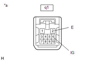
q1-6 (IG) - Body ground |
Engine switch on (IG) |
11 to 14 V |
|
q1-6 (IG) - Body ground |
Engine switch off |
Below 1 V |
(c) Measure the resistance according to the value(s) in the table below.
Standard Resistance:
|
Tester Connection | Condition |
Specified Condition |
|---|---|---|
|
q1-2 (E) - Body ground |
Always | Below 1 Ω |
| OK | |
REPLACE ROOF SUNSHADE ECU (SLIDING ROOF DRIVE GEAR ASSEMBLY)
|
| NG | |
REPAIR OR REPLACE HARNESS OR CONNECTOR |
|
11. | INSPECT PANORAMIC MOON ROOF SWITCH (ROOF CONSOLE BOX SUB-ASSEMBLY) |
(a) Remove the panoramic moon roof switch (roof console box sub-assembly).
Click here
(b) Inspect the panoramic moon roof switch (roof console box sub-assembly).
Click here
| NG | |
REPLACE PANORAMIC MOON ROOF SWITCH (ROOF CONSOLE BOX SUB-ASSEMBLY)
|
|
|
12. | CHECK HARNESS AND CONNECTOR (SLIDING ROOF ECU (SLIDING ROOF DRIVE GEAR ASSEMBLY) - PANORAMIC MOON ROOF SWITCH (ROOF CONSOLE BOX SUB-ASSEMBLY) AND BODY GROUND) |
(a) Disconnect the q2 roof sunshade ECU (sliding roof drive gear assembly) connector.
(b) Disconnect the q1 sliding roof ECU (sliding roof drive gear assembly) connector.
(c) Disconnect the V14 panoramic moon roof switch (roof console box sub-assembly) connector.
(d) Measure the resistance according to the value(s) in the table below.
Standard Resistance:
|
Tester Connection | Condition |
Specified Condition |
|---|---|---|
|
q1-10 (ROOF OPEN) - V14-5 (OPN) |
Always | Below 1 Ω |
|
q1-10 (ROOF OPEN) or V14-5 (OPN) - Body ground |
Always | 10 kΩ or higher |
|
q1-8 (ROOF CLOSE) - V14-4 (CLS) |
Always | Below 1 Ω |
|
q1-8 (ROOF CLOSE) or V14-4 (CLS) - Body ground |
Always | 10 kΩ or higher |
|
q1-4 (VENT) - V14-19 (B) |
Always | Below 1 Ω |
|
q1-4 (VENT) or V14-19 (B) - Body ground |
Always | 10 kΩ or higher |
|
q1-5 (SHADE OPEN) - V14-3 (UP) |
Always | Below 1 Ω |
|
q1-5 (SHADE OPEN) or V14-3 (UP) - Body ground |
Always | 10 kΩ or higher |
|
q1-9 (SHADE CLOSE) - V14-18 (DOWN) |
Always | Below 1 Ω |
|
q1-9 (SHADE CLOSE) or V14-18 (DOWN) - Body ground |
Always | 10 kΩ or higher |
|
q1-2 (E) - Body ground |
Always | Below 1 Ω |
|
V14-15(GND) - Body ground |
Always | Below 1 Ω |
| OK | |
REPLACE SLIDING ROOF ECU (SLIDING ROOF DRIVE GEAR ASSEMBLY)
|
| NG | |
REPAIR OR REPLACE HARNESS OR CONNECTOR |
|
13. | CHECK HARNESS AND CONNECTOR (ROOF SUNSHADE ECU (SLIDING ROOF DRIVE GEAR ASSEMBLY) - BATTERY AND BODY GROUND) |
| (a) Disconnect the q2 roof sunshade ECU (sliding roof drive gear assembly) connector. |
|
(b) Measure the voltage according to the value(s) in the table below.
Standard Voltage:
|
Tester Connection | Condition |
Specified Condition |
|---|---|---|
|
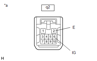
q2-6 (IG) - Body ground |
Engine switch on (IG) |
11 to 14 V |
|
q2-6 (IG) - Body ground |
Engine switch off |
Below 1 V |
(c) Measure the resistance according to the value(s) in the table below.
Standard Resistance:
|
Tester Connection | Condition |
Specified Condition |
|---|---|---|
|
q2-2 (E) - Body ground |
Always | Below 1 Ω |
| OK | |
REPLACE SLIDING ROOF ECU (SLIDING ROOF DRIVE GEAR ASSEMBLY)
|
| NG | |
REPAIR OR REPLACE HARNESS OR CONNECTOR |
READ NEXT:
 Components
COMPONENTS ILLUSTRATION
*1 SLIDING ROOF GLASS SUB-ASSEMBLY
*2 SLIDING ROOF SIDE GARNISH LH
*3 SLIDING ROOF SIDE GARNISH RH
*4 SLIDING ROOF WEATHERSTRIP
Removal
REMOVAL CAUTION / NOTICE / HINT
The necessary procedures (adjustment, calibration, initialization or registration) that must be performed after parts are removed and installed, or replaced during s
SEE MORE:
On-vehicle Inspection
ON-VEHICLE INSPECTION PROCEDURE
1. INSPECT COOLING FAN SYSTEM CAUTION: To prevent injury due to contact with an operating cooling fan, keep your hands and clothing away from the cooling fan when inspecting the cooling fan system.
(a) Connect the Techstream to the DLC3.
(b) Turn the ignition s
Reassembly
REASSEMBLY CAUTION / NOTICE / HINT
HINT:
Use the same procedure for the RH side and LH side.
The following procedure is for the LH side.
PROCEDURE 1. INSTALL HEADLIGHT COVER (for LED Type Turn Signal Light)
(a) Install the 2 headlight covers.
2. INSTALL
