Toyota Camry (XV70): Parts Location
Toyota Camry Repair Manual XV70 (2018-2024) / Engine, Hybrid System / Cruise Control / Front Camera System / Parts Location
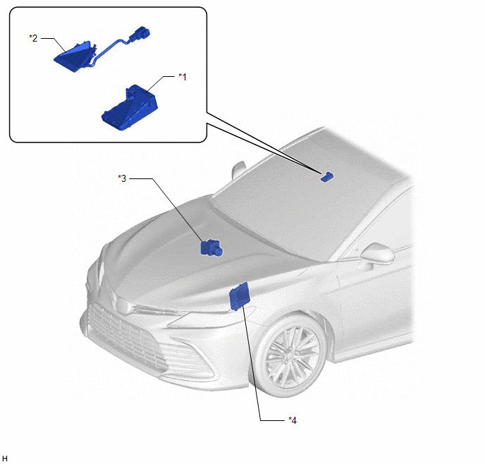
PARTS LOCATION
ILLUSTRATION
|
*1 | FORWARD RECOGNITION CAMERA |
*2 | FORWARD RECOGNITION WITH HEATER HOOD SUB-ASSEMBLY |
|
*3 | SKID CONTROL ECU (BRAKE ACTUATOR ASSEMBLY) |
*4 | ECM |
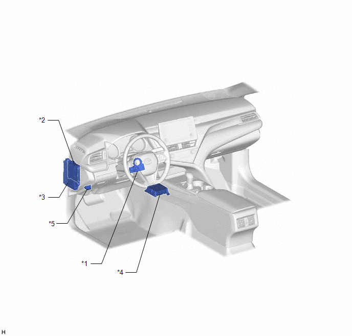
ILLUSTRATION
|
*1 | STEERING SENSOR |
*2 | MAIN BODY ECU (MULTIPLEX NETWORK BODY ECU) |
|
*3 | INSTRUMENT PANEL JUNCTION BLOCK ASSEMBLY - ECU-IG1 NO. 3 FUSE |
*4 | AIRBAG SENSOR ASSEMBLY |
|
*5 | DLC3 |
- | - |
READ NEXT:
 System Diagram
SYSTEM DIAGRAM
How To Proceed With Troubleshooting
CAUTION / NOTICE / HINT
HINT:
Before performing troubleshooting for the front camera system, perform troubleshooting for the pre-collision system.
Click here
If a pre-collision system rela
Utility
UTILITY Recognition Camera/Target Position Memory
HINT: Recognition Camera/Target Position Memory is used to enter required information into the forward recognition camera.
(a) Perform Recognition
SEE MORE:
Terminals Of Ecu
TERMINALS OF ECU
NOTICE:
DTCs may be output when connectors are disconnected during inspection. Therefore, be sure to clear the DTCs using the Techstream once the inspection has been completed.
Do not apply excessive force to the forward recognition camera connector.
*A Be
Replacement
REPLACEMENT CAUTION / NOTICE / HINT
The necessary procedures (adjustment, calibration, initialization, or registration) that must be performed after parts are removed and installed, or replaced during automatic transaxle fluid replacement are shown below. Necessary Procedures After Parts Removed/I
© 2023-2026 Copyright www.tocamry.com
