
Toyota Camry (XV70): Parts Location
PARTS LOCATION
ILLUSTRATION
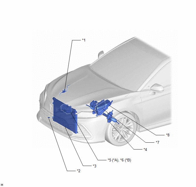
|
*A | for A25A-FKS |
*B | for 2GR-FKS |
|
*1 | AIR CONDITIONER PRESSURE SENSOR |
*2 | THERMISTOR ASSEMBLY |
|
*3 | COOLER CONDENSER ASSEMBLY |
*4 | POWER STEERING ECU (RACK AND PINION POWER STEERING GEAR ASSEMBLY) |
|
*5 | COMPRESSOR ASSEMBLY WITH PULLEY - COOLER COMPRESSOR ASSEMBLY (COMPRESSOR SOLENOID) |
*6 | COMPRESSOR ASSEMBLY WITH MAGNETIC CLUTCH - COOLER COMPRESSOR ASSEMBLY (COMPRESSOR SOLENOID) - MAGNET CLUTCH ASSEMBLY |
|
*7 | ECM |
*8 | ENGINE ROOM RELAY BLOCK AND JUNCTION BLOCK ASSEMBLY - HTR FUSE - A/C COMP FUSE - Magnetic Clutch Relay (for 2GR-FKS) |
ILLUSTRATION
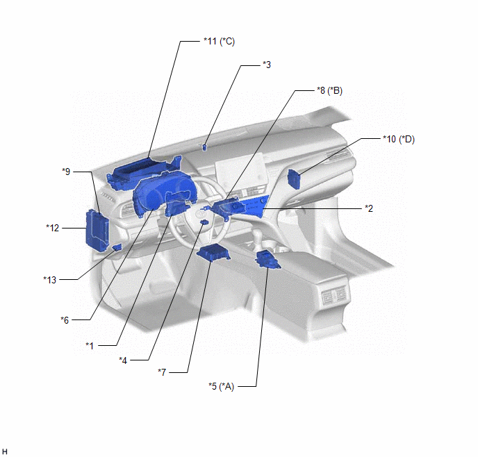
|
*A | w/ Electric Parking Brake System |
*B | w/ Manual (SOS) Switch |
|
*C | w/ Headup Display System |
*D | w/ Parking Support Brake System |
|
*1 | AIR CONDITIONING AMPLIFIER ASSEMBLY |
*2 | AIR CONDITIONING CONTROL ASSEMBLY |
|
*3 | AUTOMATIC LIGHT CONTROL SENSOR |
*4 | COOLER (ROOM TEMP. SENSOR) THERMISTOR |
|
*5 | ECO SWITCH ASSEMBLY (ELECTRIC PARKING BRAKE SWITCH ASSEMBLY) |
*6 | COMBINATION METER ASSEMBLY |
|
*7 | AIRBAG SENSOR ASSEMBLY |
*8 | DCM (TELEMATICS TRANSCEIVER) |
|
*9 | MAIN BODY ECU (MULTIPLEX NETWORK BODY ECU) |
*10 | CLEARANCE WARNING ECU ASSEMBLY |
|
*11 | METER MIRROR SUB-ASSEMBLY |
*12 | INSTRUMENT PANEL JUNCTION BLOCK ASSEMBLY - ECU-B NO. 2 FUSE - ECU-IG1 NO. 3 FUSE - ECU-IG1 NO. 4 FUSE - ECU-ACC FUSE |
|
*13 | DLC3 |
- | - |
ILLUSTRATION
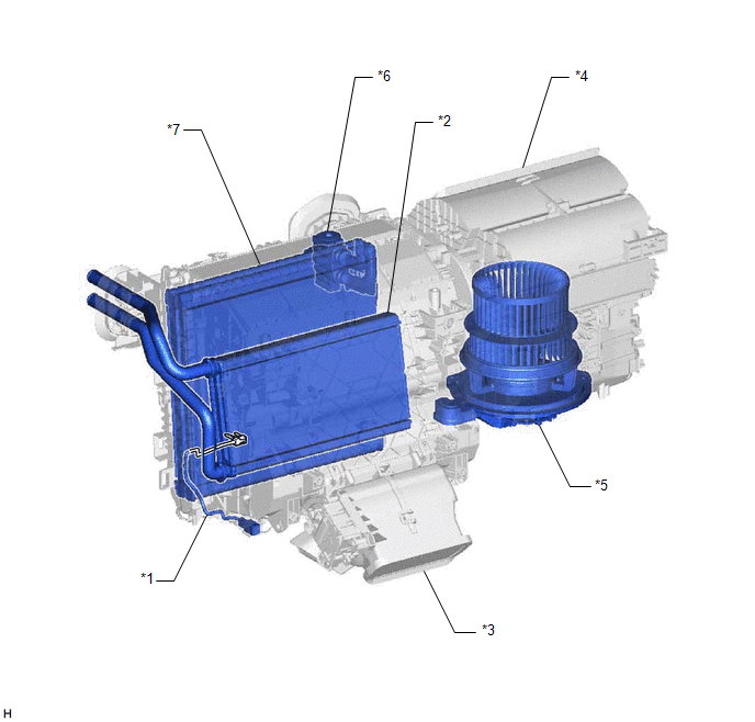
|
*1 | NO. 1 COOLER THERMISTOR |
*2 | HEATER RADIATOR UNIT SUB-ASSEMBLY |
|
*3 | AIR CONDITIONING RADIATOR ASSEMBLY |
*4 | BLOWER ASSEMBLY |
|
*5 | BLOWER MOTOR WITH FAN SUB-ASSEMBLY |
*6 | COOLER EXPANSION VALVE |
|
*7 | NO. 1 COOLER EVAPORATOR SUB-ASSEMBLY |
- | - |
ILLUSTRATION
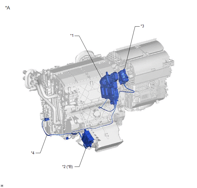
|
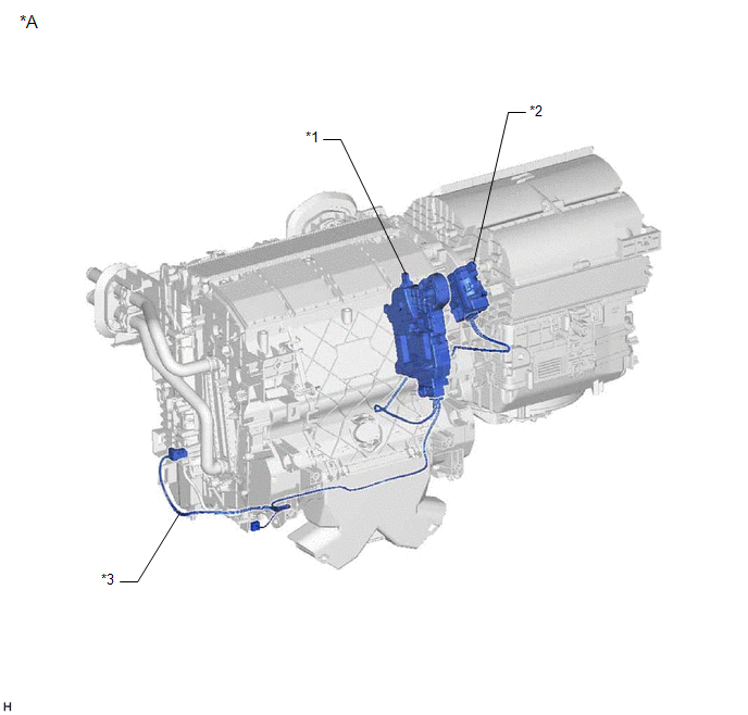
*A | for Dual Type |
*B | w/ Rear Center Register |
|
*1 | NO. 1 AIR CONDITIONING RADIATOR DAMPER SERVO SUB-ASSEMBLY |
*2 | NO. 2 AIR CONDITIONING RADIATOR DAMPER SERVO SUB-ASSEMBLY |
|
*3 | NO. 1 BLOWER DAMPER SERVO SUB-ASSEMBLY |
*4 | AIR CONDITIONING HARNESS ASSEMBLY |
ILLUSTRATION
|
*A | for Single Type |
- | - |
|
*1 | NO. 1 AIR CONDITIONING RADIATOR DAMPER SERVO SUB-ASSEMBLY |
*2 | NO. 1 BLOWER DAMPER SERVO SUB-ASSEMBLY |
|
*3 | AIR CONDITIONING HARNESS ASSEMBLY |
- | - |
READ NEXT:
 System Diagram
SYSTEM DIAGRAM
System Description
SYSTEM DESCRIPTION COMMUNICATION SYSTEM FUNCTION
(a) The air conditioning amplifier assembly communicates with each ECU via CAN communication and LIN communication. Additionally, the air conditioning
How To Proceed With Troubleshooting
CAUTION / NOTICE / HINT
HINT:
Use the following procedure to troubleshoot the air conditioning system.
*: Use the Techstream.
PROCEDURE
1. VEHICLE BROUGHT TO WORKSHOP
NEX
SEE MORE:
ABS Malfunction (C1296)
DESCRIPTION If a malfunction in the speed sensor signal circuit or yaw rate and acceleration sensor (airbag sensor assembly) circuit occurs, the 4WD ECU assembly will output this DTC.
The airbag sensor assembly has a built-in yaw rate and acceleration sensor.
DTC No. Detection Item
DT
Removal
REMOVAL CAUTION / NOTICE / HINT
HINT:
Use the same procedure for the RH side and LH side.
The following procedure is for the LH side.
The front speed sensor rotor is a component of the front axle hub sub-assembly. If the front speed sensor rotor is malfunctioning, replace the front axl
