Toyota Camry (XV70): Power Source Circuit
DESCRIPTION
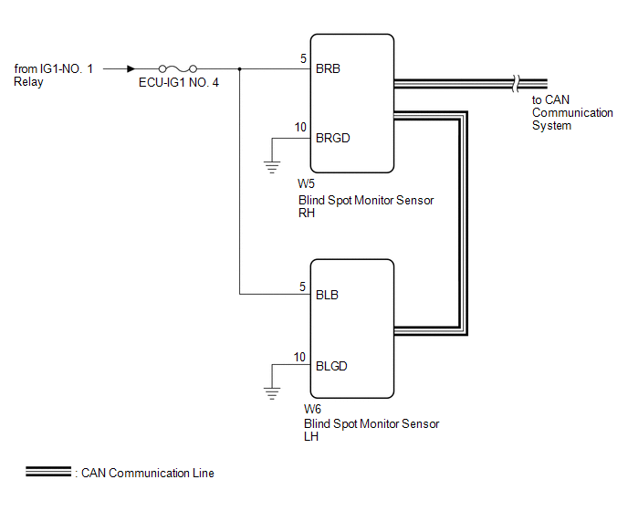
This circuit provides power to operate the blind spot monitor sensor.
WIRING DIAGRAM
CAUTION / NOTICE / HINT
NOTICE:
Inspect the fuses for circuits related to this system before performing the following procedure.
PROCEDURE
| 1. |
CHECK HARNESS AND CONNECTOR (BLIND SPOT MONITOR SENSOR RH POWER SOURCE) |
(a) Disconnect the W5 blind spot monitor sensor RH connector.
(b) Measure the voltage according to the value(s) in the table below.
Standard Voltage:
|
Tester Connection | Condition |
Specified Condition |
|---|---|---|
|
W5-5 (BRB) - Body ground |
Engine switch on (IG) |
11 to 14 V |
|
W5-5 (BRB) - Body ground |
Engine switch off | Below 1 V |
| NG | .gif) | REPAIR OR REPLACE HARNESS OR CONNECTOR |
|
.gif)
| 2. |
CHECK HARNESS AND CONNECTOR (BLIND SPOT MONITOR SENSOR RH - BODY GROUND) |
(a) Measure the resistance according to the value(s) in the table below.
Standard Resistance:
|
Tester Connection | Condition |
Specified Condition |
|---|---|---|
|
W5-10 (BRGD) - Body ground |
Always | Below 1 Ω |
| NG | | REPAIR OR REPLACE HARNESS OR CONNECTOR |
|
| 3. |
CHECK HARNESS AND CONNECTOR (BLIND SPOT MONITOR SENSOR LH POWER SOURCE) |
(a) Disconnect the W6 blind spot monitor sensor LH connector.
(b) Measure the voltage according to the value(s) in the table below.
Standard Voltage:
|
Tester Connection | Condition |
Specified Condition |
|---|---|---|
|
W6-5 (BLB) - Body ground |
Engine switch on (IG) |
11 to 14 V |
|
W6-5 (BLB) - Body ground |
Engine switch off | Below 1 V |
| NG | | REPAIR OR REPLACE HARNESS OR CONNECTOR |
|
| 4. |
CHECK HARNESS AND CONNECTOR (BLIND SPOT MONITOR SENSOR LH - BODY GROUND) |
(a) Measure the resistance according to the value(s) in the table below.
Standard Resistance:
|
Tester Connection | Condition |
Specified Condition |
|---|---|---|
|
W6-10 (BLGD) - Body ground |
Always | Below 1 Ω |
| OK | | PROCEED TO NEXT SUSPECTED AREA SHOWN IN PROBLEM SYMPTOMS TABLE
|
.gif)
| NG | | REPAIR OR REPLACE HARNESS OR CONNECTOR |
READ NEXT:
 Clearance Warning Buzzer
ComponentsCOMPONENTS ILLUSTRATION
*A for 7 Inch Display
*B for 9 Inch Display
*1 CENTER INSTRUMENT CLUSTER FINISH PANEL ASSEMBLY
*2 CENTER INSTRUMENT CLUSTER FINI
Components
COMPONENTS ILLUSTRATION
*1 CLEARANCE WARNING ECU ASSEMBLY
*2 ECU INTEGRATION BOX RH
*3 LOWER INSTRUMENT PANEL SUB-ASSEMBLY
- -
N*m (kgf*cm, ft.*lbf
SEE MORE:
Washer Motor Circuit
DESCRIPTION When the windshield washer motor and pump assembly receives signals from the windshield wiper switch assembly it operates to spray washer fluid from the washer nozzle sub-assemblies. WIRING DIAGRAM
CAUTION / NOTICE / HINT
NOTICE:
Inspect the fuses for circuits related to thi
Brake Switch "A" Circuit Open (P057113)
DESCRIPTION When the brakes are applied by the dynamic radar cruise control system, the skid control ECU (brake actuator assembly) operates the stop light switch assembly to illuminate the stop lights.
If the ECM receives a signal from the skid control ECU (brake actuator assembly) indicating a ma
