Toyota Camry (XV70): Rear Axle Hub Bolt(w/o Electric Parking Brake System)
Components
COMPONENTS
ILLUSTRATION
|
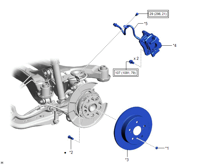
*1 | PARKING BRAKE SHOE ADJUSTING HOLE PLUG |
*2 | REAR AXLE HUB BOLT |
|
*3 | REAR DISC |
*4 | REAR DISC BRAKE CALIPER ASSEMBLY |
|
*5 | REAR FLEXIBLE HOSE |
- | - |
.png) |
Tightening torque for "Major areas involving basic vehicle performance such as moving/turning/stopping" : N*m (kgf*cm, ft.*lbf) |
● | Non-reusable part |
Replacement
REPLACEMENT
CAUTION / NOTICE / HINT
HINT:
- Use the same procedure for the RH side and LH side.
- The following procedure is for the LH side.
PROCEDURE
1. REMOVE REAR WHEEL
Click here
.gif)
2. SEPARATE REAR DISC BRAKE CALIPER ASSEMBLY
(a) Remove the bolt and separate the rear flexible hose from the rear flexible hose bracket.
(b) Remove the 2 bolts and separate the rear disc brake caliper assembly from the rear axle carrier sub-assembly.
NOTICE:
Use wire or an equivalent tool to keep the rear disc brake caliper assembly from hanging by the rear flexible hose.
3. REMOVE PARKING BRAKE SHOE ADJUSTING HOLE PLUG
Click here
4. REMOVE REAR DISC
Click here
5. REMOVE REAR AXLE HUB BOLT
| (a) Temporarily install 2 service nuts to the rear axle hub bolts as shown in the illustration. Recommended Service Nut: Thread diameter: 12.0 mm (0.472 in.) Thread pitch: 1.5 mm (0.0591 in.) NOTICE: Install the service nuts to prevent damage to the rear axle hub bolts. |
|
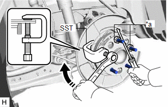
(b) Using SST and a screwdriver or an equivalent tool to hold the rear axle hub and bearing assembly, remove the rear axle hub bolt.
SST: 09611-12010
NOTICE:
Do not damage the threads of the rear axle hub bolts.
6. INSTALL REAR AXLE HUB BOLT
| (a) Temporarily install a new rear axle hub bolt to the rear axle hub and bearing assembly. |
|
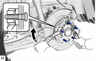
(b) Install a washer and service nut to the rear axle hub bolt as shown in the illustration.
Recommended Service Nut:
Thread diameter: 12.0 mm (0.472 in.)
Thread pitch: 1.5 mm (0.0591 in.)
HINT:
Recommended washer thickness is 5 mm (0.197 in.) or more.
(c) Using a screwdriver or an equivalent tool to hold the rear axle hub and bearing assembly, install the rear axle hub bolt by tightening the service nut.
NOTICE:
- Install the service nuts to prevent damage to the rear axle hub bolts.
- Do not damage the threads of the rear axle hub bolts.
(d) Remove the 3 service nuts and washer from the 3 rear axle hub bolts.
7. INSTALL REAR DISC
Click here
8. INSTALL PARKING BRAKE SHOE ADJUSTING HOLE PLUG
Click here
9. INSTALL REAR DISC BRAKE CALIPER ASSEMBLY
(a) Install the rear disc brake caliper assembly to the rear axle carrier sub-assembly with the 2 bolts.
Torque:
107 N
READ NEXT:
 Components
COMPONENTS ILLUSTRATION
*1 REAR DIFFERENTIAL CARRIER ASSEMBLY
*2 WIRE HARNESS CLAMP BRACKET
*3 REAR UPPER DIFFERENTIAL MOUNT STOPPER
*4 REAR LOWER DIFFERENTIAL MO
Removal
REMOVAL CAUTION / NOTICE / HINT
The necessary procedures (adjustment, calibration, initialization, or registration) that must be performed after parts are removed and installed, or replaced during r
SEE MORE:
Cruise Control Input Processor (P160700)
DESCRIPTION When the ECM detects that it is not functioning normally, DTC P160700 is stored.
DTC No. Detection Item
DTC Detection Condition Trouble Area
MIL DTC Output from
P160700 Cruise Control Input Processor
When the ignition switch is ON and control of vehi
Inspection
INSPECTION PROCEDURE 1. INSPECT WATER INLET WITH THERMOSTAT SUB-ASSEMBLY
CAUTION:
Do not put your hands into the water that has been heated for the inspection.
Touching the heated water could result in burns.
HINT: The valve opening temperature is inscribed on the water inlet wit
