Toyota Camry (XV70): Removal
REMOVAL
CAUTION / NOTICE / HINT
The necessary procedures (adjustment, calibration, initialization or registration) that must be performed after parts are removed and installed, or replaced during front door window frame moulding removal/installation are shown below.
Necessary Procedure After Parts Removed/Installed/Replaced|
Replaced Part or Performed Procedure |
Necessary Procedure | Effect/Inoperative Function when Necessary Procedure not Performed |
Link |
|---|---|---|---|
|
Disconnect cable from negative battery terminal |
Perform steering sensor zero point calibration |
Lane Tracing Assist System |
|
|
Pre-collision System | |||
|
Memorize steering angle neutral point |
Parking Assist Monitor System |
| |
|
Panoramic View Monitor System |
| ||
| Initialize power window control system |
|
|
HINT:
- Use the same procedure for the RH side and LH side.
- The following procedure is for the LH side.
PROCEDURE
1. REMOVE FRONT DOOR BELT MOULDING ASSEMBLY
Click here .gif)
2. REMOVE FRONT DOOR PANEL PROTECTOR
Click here
3. REMOVE FRONT DOOR GLASS RUN
Click here
4. DISCONNECT FRONT DOOR WEATHERSTRIP
| (a) Disengage the 2 clips and disconnect the front door weatherstrip. |
|
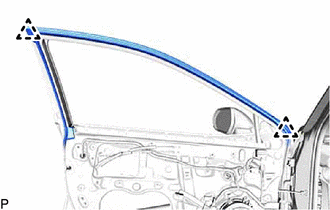
5. REMOVE FRONT DOOR REAR WINDOW FRAME MOULDING
HINT:
When removing the front door rear window frame moulding, heat the vehicle body and front door rear window frame moulding using a heat light.
Heating Temperature|
Item | Temperature |
|---|---|
|
Vehicle Body | 40 to 60 |
READ NEXT:
 Installation
INSTALLATION CAUTION / NOTICE / HINT
HINT:
Use the same procedure for the RH side and LH side.
The following procedure is for the LH side.
PROCEDURE 1. INSTALL FRONT DOOR UPPER WIND
Front Pillar Upper Cover
ComponentsCOMPONENTS ILLUSTRATION
*1 FRONT DOOR FRONT LOWER FRAME UPPER COVER
- - RemovalREMOVAL CAUTION / NOTICE / HINT
The necessary procedures (adjustment, calibration
SEE MORE:
How To Proceed With Troubleshooting
HOW TO PROCEED WITH TROUBLESHOOTING OPERATION FLOW
HINT: Perform troubleshooting in accordance with the procedure below. The following is an outline of basic troubleshooting procedure. Confirm the troubleshooting procedure for the circuit you are working on before beginning troubleshooting.
1.VE
Check Bus 2 Lines for Short Circuit
DESCRIPTION There may be a short circuit between the CAN main bus lines and/or CAN branch lines when the resistance between terminals 18 (CA4H) and 17 (CA4L) of the central gateway ECU (network gateway ECU) is below 54 Ω.
Symptom Trouble Area
Resistance between terminals 18 (CA4
